


Chapter 2 NI SPEEDY-33 Functional Description and Interface
NI SPEEDY-33 User Manual 2-4 ni.com
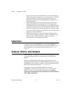
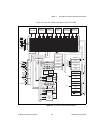
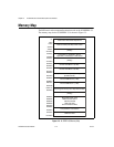
Memory Map
The DSP runs in microcomputer/bootloader mode on the NI SPEEDY-33.
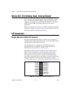
The memory map for the NI SPEEDY-33 is shown in Figure 2-3.
Figure 2-3. NI SPEEDY-33 Memory Map
Reserved for Bootloader Operations
0h
FFFh
External RAM (1008 KB) 5 Wait States
1000h
3FFFFh
(Empty)
40000h
3FFFFFh
Flash Memory (2048 KB in Space,
Byte-Wide, Lowest Byte) 7 Wait States
400000h
47FFFFh
(Empty)
480000h
7FFFFFh
Internal RAM Block 2 (64 KB)
800000h
803FFFh
Internal RAM Block 3 (64 KB)
804000h
807FFFh
Peripheral Bus Memory-Mapped Registers
(24 KB Internal)
808000h
8097FFh
Internal RAM Block 0 (4 KB)
809800h
809BFFh
Internal RAM Block 1 (4 KB)
809C00h
809FC0h
U
ser Program Interrupt and Trap Branch Table
809FC1h
809FFFh
(Empty)
Board Status/CTL, XXF
USB Peripheral Status
USB Host EVEN
USB Host ODD
Switch Read/LED Write
80B000h
80B003h
80B004h
80B005h
80B007h
CompactFlash Control/Data
C00000h
C0000Fh
USB Boot Area
FFF000h
FFFFFFh