


Appendix A Pinout Information
NI-FBUS Monitor User Manual A-2 ni.com
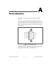
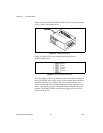
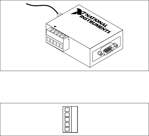
Figure A-2 shows the PCMCIA-FBUS cable. An arrow on the cable points
to pin 1 of the screw terminal block.
Figure A-2. PCMCIA-FBUS Cable
Figure A-3 shows J2, the screw terminal block pinout for the
PCMCIA-FBUS cable.
Figure A-3. Screw Terminal Block Pinout
All of the signals on the screw terminal block provide a direct connection
to the 9-pin DSUB. Pins 2 and 4 of the J2 screw terminal block provide an
alternate connection to the fieldbus. The screw terminal block is not a
second, independent link. National Instruments provides the Power+ and
Power– connections as passive connections from the DSUB to the screw
terminal. The PCMCIA-FBUS itself does not supply power to or draw
power from these pins.
J2
J1
PCMCIA-FBUS, PORT 1
V-
D-
SH
D+
V+
1
2
3
4
5
Power
–
Data
–
Shield
Data +
Power +