


Appendix B Cabling Requirements for PXI-8460 Low-Speed CAN
© National Instruments Corporation B-5 PXI-846x and NI-CAN for Windows NT
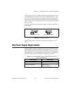
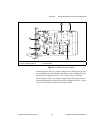
Low-Speed Termination
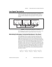
Every device on the low-speed CAN network requires a termination
resistor for each CAN data line: R
RTH
for CAN_H and R
RTL
for CAN_L.
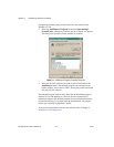
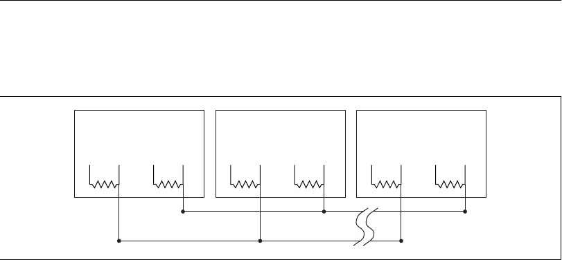
Figure B-4 shows termination resistor placement in a low-speed CAN
network.
Figure B-4. Termination Resistor Placement for Low-Speed CAN
The following sections explain how to determine the correct resistor values
for your PXI-8460, and how to replace those resistors, if necessary.
Determining the Necessary Termination Resistance for Your Board
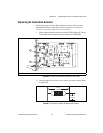
Unlike high-speed CAN, low-speed CAN requires termination at the
low-speed CAN transceiver instead of on the cable. The termination
requires one resistor for each CAN line. This configuration allows the
Philips fault-tolerantCAN transceiverto detect anyof seven networkfaults.
You can useyour PXI-8460 to connect to alow-speedCAN network having
from two to 32 nodes as specified by Philips (including the port on the
PXI-8460 as a node). You can also use the PXI-8460 to communicate with
individual low-speed CAN devices. It is important to determine the overall
termination of your existing network, or the termination of your individual
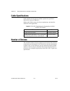
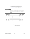
device, before connecting it to a PXI-8460 port. Philips recommends an
overall RTH and RTL termination of 100 to 500 Ω (each) for a properly
terminated low-speed network. The overall network termination may be
determined as follows:
Low-speed
CAN Device
RTL CAN_L RTH CAN_H
Low-speed
CAN Device
RTL CAN_L RTH CAN_H
Low-speed
CAN Device
RTL CAN_L RTH CAN_H
CAN_H
CAN_L
1
R
RTH overall
†
--------------------------
1
R
RTH node 1
------------------------
1
R
RTH node 2
------------------------
1
R
RTH node 3
------------------------
1
R
RTH node n
-------------------------+++=