


Appendix C Cabling Requirements for PXI-8461 High-Speed CAN
PXI-846x and NI-CAN for Windows NT C-2 ni.com
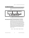
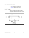
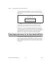
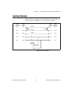
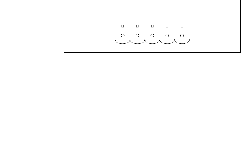
The 5-pin Combicon-style pluggable screw terminal follows the pinout
required by the DeviceNet Specification. Figure C-2 shows the pinout for
this connector.
Figure C-2. Pinout for 5-Pin Combicon-Style Pluggable Screw Terminal
CAN_H and CAN_L are signal lines that carry the data on the CAN
network. These signals should be connected using twisted-pair cable.
The V+ and V– pins are used to supply bus power to the CAN physical
layer if external power is required for the CAN physical layer. If internal
powerfor the CAN physical layer is used,the V– pinservesasthereference
ground for CAN_H and CAN_L. See the next section, Power Supply
Information for the High-Speed CAN Ports, for more information.
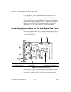
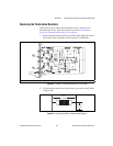
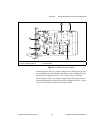
Power Supply Information for the High-Speed CAN Ports
For the PXI-8461, a jumper controls the source of power for the CAN
physical layer. For the one-port boards and port one of the two-port boards,
power is configured with jumper J5. For port two of the two-port boards,
poweris configured withjumper J6. The location of thesejumpers is shown
in Figure C-3.
CAN_L
V–
CAN_H
V+
Shield
12345