


5-1
VisuaLink 128/384 General Description
Specifications
General Specifications
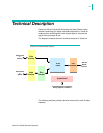
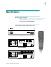
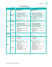
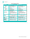
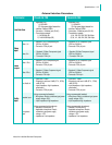
The following diagrams illustrate the VisuaLink 128 and VisuaLink 384
units. All front and rear panel connections are shown. (See the
General Parameters table for dimensions.)
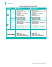
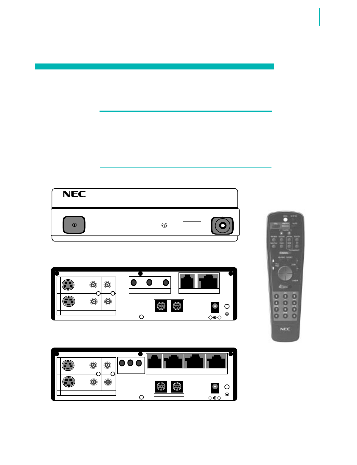
VisuaLink 128/384 Front & Rear Panels and Remote Control
POWER HEADSET
POWER
LINE
B1 B2-B6
Front Panel
+
+
+
+
+
DC IN 5V
+
-
Serial1 Serial2/RMT
O
U
T
I
N
VIDEO2 VIDEO1 AUDIO
+
+
TEL S/T LINE
MIC1 MIC2 MIC3
+
+
+
+
+
DC IN 5V
+
-
Serial1 Serial2/RMT
O
U
T
I
N
VIDEO2 VIDEO1 AUDIO
+
+
TEL S/T LINE S/T LINE S/T LINE
MIC1 MIC2 MIC3
VisuaLink 128 Rear Panel
VisuaLink 384 Rear Panel
Wireless
Control
Remote