


Setting Up the System 2-11
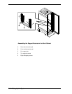
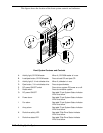
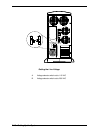
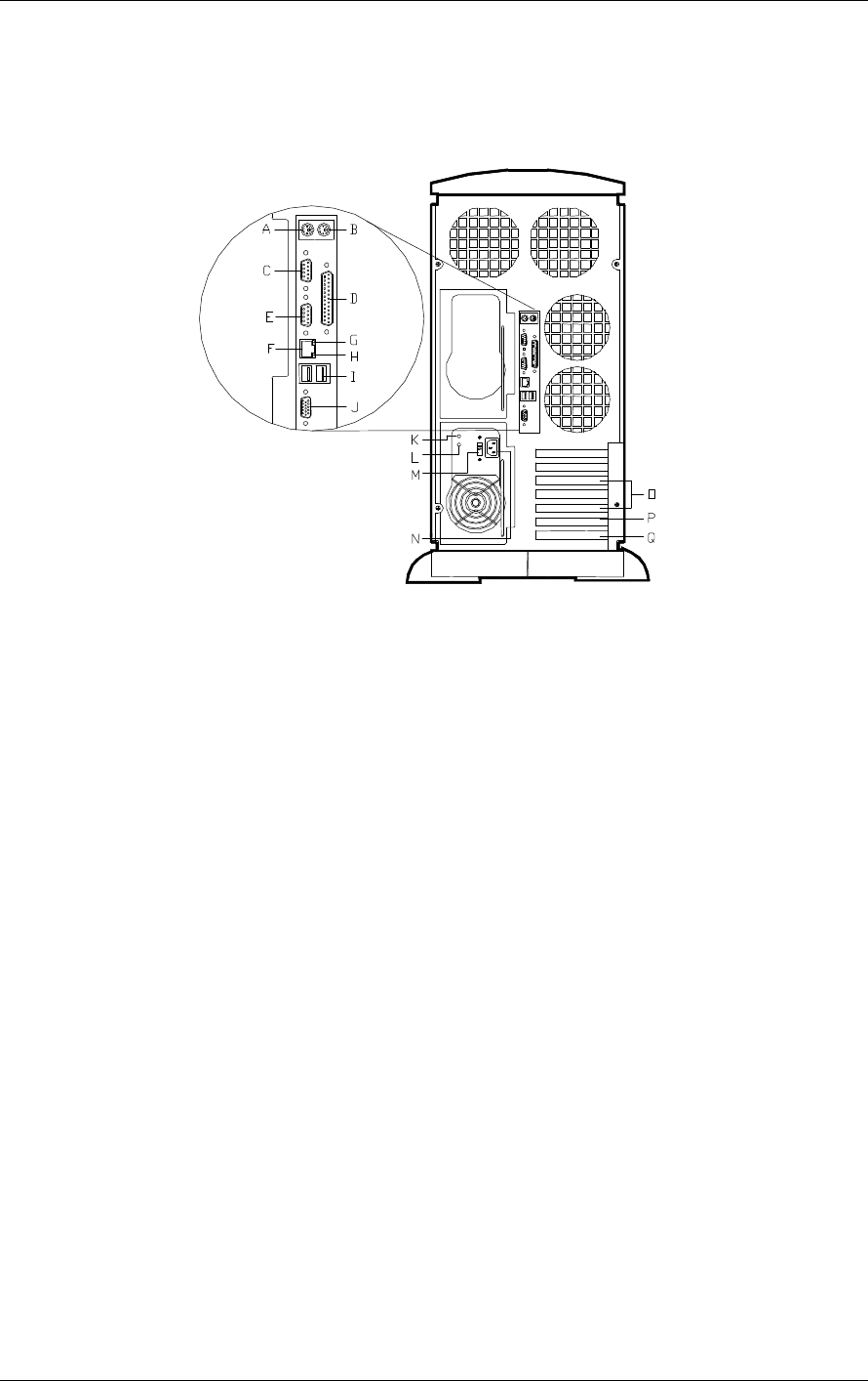
Rear View
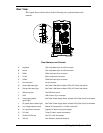
This figure shows the location of the following rear system features and
controls.
Rear Features and Controls
A. Keyboard PS/2-compatible 6-pin mini-DIN connector.
B. Mouse PS/2-compatible 6-pin mini-DIN connector.
C. COM1 COM1 serial port 9-pin connector.
D. Printer 25-pin parallel port connector.
E. COM2 COM2 serial port 9-pin connector.
F. LAN connector RJ-45 connector.
G. Green LAN status light See Table "LAN Status Indicator LEDs (I/O Panel)" that follows.
H. Orange LAN status light See Table "LAN Status Indicator LEDs (I/O Panel)" that follows.
I. USB connectors Two USB Connectors.
J. VGA VGA monitor 15-pin connector.
K. Power supply status
(green light)
See Table "Power Supply Status Indicator LEDs (Rear Panel)" that follows.
L. DC power status (amber light) See Table "Power Supply Status Indicator LEDs (Rear Panel)" that follows.
M Line voltage selector switch Selects AC input power of 115 VAC or 230 VAC.
N. AC input power connector Supplies AC power to the power supply.
O. PCI slots Three PCI add-in board slot locations.
P. Combo PCI/ISA slot One PCI or ISA slot location.
Q. ISA slot One ISA add-in board slot locations.