


8
5
6
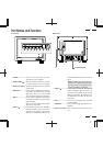
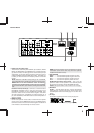
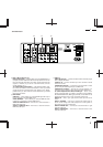
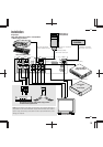
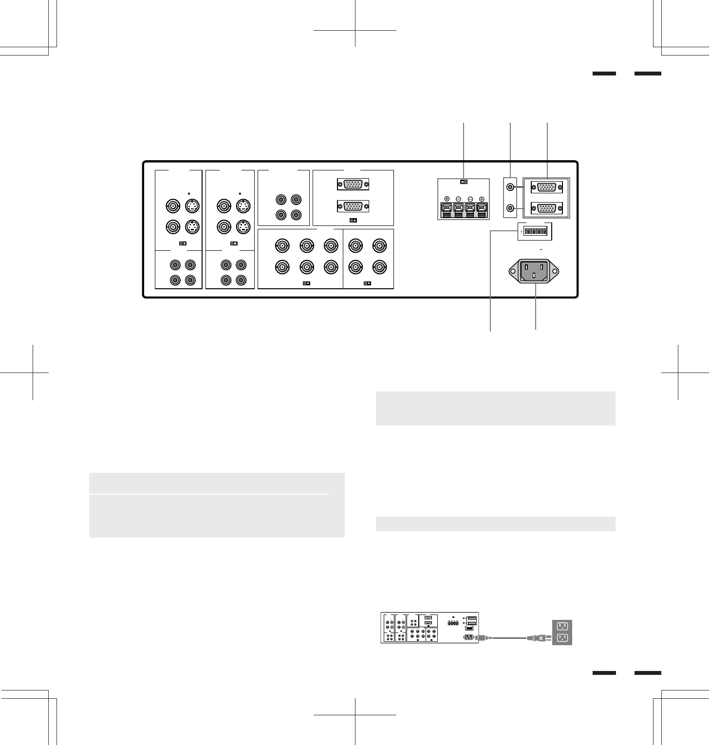
Terminal Board
BA
C
VIDEO 1 VIDEO 2 RGB AUDIO RGB 1
REMOTE
PC/EXT CTL
DIP SW
AC IN
SPEAKER SELECT
EXT SPEAKER
RGB 2
AUDIO AUDIO
HIGH 75Ω
R
MONO
IN
THROUGH
OUT
IN
THROUGH
OUT
THROUGH
OUT
IN
BNC S
HIGH 75Ω
THROUGH
OUT
IN
R
THROUGH
OUT
IN
R
THROUGH
OUT
IN
BNC S
HIGH 75Ω
IN
THROUGH
OUT
R/C
R
/P
R
G/Y/Y B/C
B
/P
B
H/CS V
HIGH 75ΩHIGH 75Ω
SPEAKRES MUST
HAVE MORE THAN
5WATT RATING
INPEDANCE 8 OHM
RIGHT LEFT
INT EXT
IN
OUT
12345678
ON
()
L
MONO
()
L
MONO
()
L
A PC/ECT CTL IN (D-Sub 15-pin)
This terminal is used when power ON/OFF, input selection, AUDIO
MUTE, PICTURE MUTE, and DEGAUSS are operated externally
(by external control). See also page 42 for external control port pin
assignments. You can also use this connector to connect your PC to
control the MultiSync XP37 Xtra/XM37 Xtra monitor. This allows you
to utilize your PC and serial communication protocol to control the
monitor.
NOTE: Select EXT. CONTROL ON by setting pin No. 6 of DIP SW
to the ON position when operating the monitor by external control.
NOTE: When in the EXT. CONTROL mode, the following
operations of the supplied wireless remote control are not possible:
Power control ON/ OFF, Input selection, and Degauss switch ON/
OFF.
PC/ECT CTL OUT (D-Sub 15-pin).....Connect to a second monitor’s
EXTERNAL CONTROL input to relay the signal input at the
EXTERNAL CONTROL IN. The EXTERNAL CONTROL OUT
terminal is used to connect several monitors together and allows
all of the monitors to be controlled by one external control. No. 6
pin (EXT. CONTROL) of DIP SW must be set to the ON position on
all of the monitors.
B REMOTE IN/OUT
Connect the optional remote cable, included with the optional
remote control, to the REMOTE IN terminal. The REMOTE OUT
terminal is used to connect several monitors together and allows all
of the monitors to be controlled by one remote control.
NOTE: Up to 50 monitors can be connected in the serial
connection. (This can be done only when the optional
supplied remoto cable is used.)
C EXT SPEAKER
RIGHT + ....... Connect RIGHT speaker positive wire here.
RIGHT - ........ Connect RIGHT speaker negative wire here.
LEFT -.......... Connect LEFT speaker negative wire here.
LEFT + .........Connect LEFT speaker positive wire here.
SPEAKER SELECT INT/EXT Select Switch.....Set to the INT
position for built-in monitor speakers. Set to the EXT position
for speakers connected to the EXT SPEAKER terminals.
NOTE: The speaker cables must be less than 3m in length.
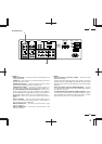
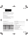
D DIP Switch
DIP SW..... This DIP switch sets Sync. Control, the Intelligent
Power Manager, external control on/off, remote control on/off,
and OSM system control on/off. See pages 17 and 18 for more
details.
E AC Input
Connect the supplied power cord’ s three-pin plug here.
D
E
VIDEO 1 VIDEO 2 RGB AUDIO RGB 1
REMOTE
PC/EXT CTL
DIP SW
AC IN
SPEAKER SELECT
EXT SPEAKER
RGB 2
AUDIO AUDIO
HIGH 75Ω
R
MONO
IN
THROUGH
OUT
IN
THROUGH
OUT
THROUGH
OUT
IN
BNC S
HIGH 75Ω
THROUGH
OUT
IN
R
THROUGH
OUT
IN
R
THROUGH
OUT
IN
BNC S
HIGH 75Ω
IN
THROUGH
OUT
R/C
R
/P
R
G/Y/Y B/C
B
/P
B
H/CS V
HIGH 75ΩHIGH 75Ω
SPEAKRES MUST
HAVE MORE THAN
5WATT RATING
INPEDANCE 8 OHM
RIGHT LEFT
INT EXT
IN
OUT
12345678
ON
()
L
MONO
()
L
MONO
()
L
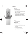
Insert the prongs completely.