


E-12
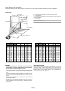
NOTE: Distances may vary +/-5%.
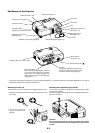
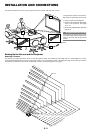
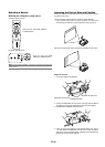
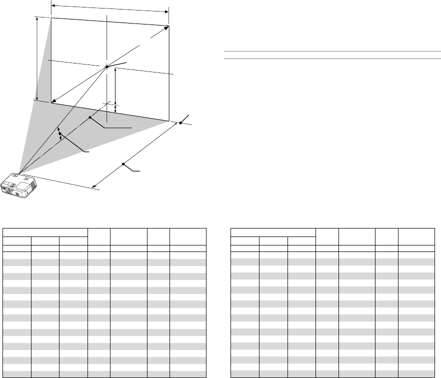
Distance Chart
B = Vertical distance between lens center and screen center
C = Throw distance
D = Vertical distance between lens center and top of screen (bottom of
screen for desktop)
α = Throw angle
Lens Center
Throw Angle (α)
Throw Distance
(
C
)
Screen center
Screen Diagonal
Screen Width
Screen Height
Screen Bottom
(
D
)
(
B
)
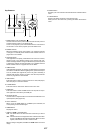
Throw Distance and Screen Size
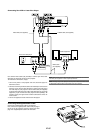
The following shows the proper relative positions of the projector and screen. Refer to the table to determine the position of installation.
α
Wide – Tele
Screen Size B C
Wide – TeleDiagonal Width Height
degree
––– - 10.0
11.8 - 9.9
11.7 - 9.8
11.6 - 9.7
11.5 - 9.6
11.4 - 9.6
11.4 - 9.6
11.4 - 9.6
11.4 - 9.5
11.4 - 9.5
11.4 - 9.5
11.4 - 9.5
11.3 - 9.5
11.3 - 9.5
11.3 - 9.5
11.3 - 9.5
11.3 - 9.5
11.3 - 9.5
α
Wide – Tele
Screen Size B C
Wide – TeleDiagonal Width Height
degree
––– - 10.0
11.8 - 9.9
11.7 - 9.8
11.6 - 9.7
11.5 - 9.6
11.4 - 9.6
11.4 - 9.6
11.4 - 9.6
11.4 - 9.5
11.4 - 9.5
11.4 - 9.5
11.4 - 9.5
11.3 - 9.5
11.3 - 9.5
11.3 - 9.5
11.3 - 9.5
11.3 - 9.5
11.3 - 9.5
D D
inch
13
15
18
24
36
43
48
50
54
60
72
90
108
120
126
144
162
180
inch
––– - 29
29 - 35
35 - 42
47 - 57
71 - 86
86 - 103
96 - 115
101 - 121
108 - 129
120 - 144
144 - 173
181 - 217
217 - 260
241 - 290
253 - 304
290 - 348
326 - 391
363 - 400
inch
5
6
7
10
15
17
19
20
22
24
29
36
44
48
51
58
65
73
mm
320
381
457
610
914
1097
1219
1280
1372
1524
1829
2286
2743
3048
3200
3658
4115
4572
mm
––– - 740
740 - 880
890 -1070
1200 -1440
1810 -2180
2180 -2620
2430 -2920
2550 -3060
2740 -3290
3050 -3660
3660 -4400
4590 -5510
5510 -6610
6130 -7350
6440 -7720
7360 -8830
8290 -9940
9210 -11050
mm
130
150
180
250
370
440
490
520
550
610
740
920
1110
1230
1290
1470
1660
1840
mm
533
635
762
1016
1524
1829
2032
2134
2286
2540
3048
3810
4572
5080
5334
6096
6858
7620
mm
427
508
610
813
1219
1463
1626
1707
1829
2032
2438
3048
3658
4064
4267
4877
5486
6096
inch
21
25
30
40
60
72
80
84
90
100
120
150
180
200
210
240
270
300
inch
17
20
24
32
48
58
64
67
72
80
96
120
144
160
168
192
216
240
inch
1
1
2
2
3
4
5
5
5
6
7
9
10
12
12
14
16
17
mm
30
40
40
60
90
110
120
120
130
150
180
220
270
300
310
350
400
440
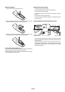
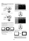
Reflecting the Image
Using a mirror to reflect your projector's image enables you to enjoy a
much larger image. Contact your NEC dealer if you need a mirror. If
you're using a mirror and your image is inverted, use the MENU and
SELECT buttons on your projector cabinet or your remote control to
correct the orientation. (See page E-27.)
WARNING
* Installing your projector on the ceiling must be done by a quali-
fied technician. Contact your NEC dealer for more information.
* Do not attempt to install the projector yourself.
• Only use your projector on a solid, level surface. If the projector falls
to the ground, you can be injured and the projector severely dam-
aged.
• Do not use the projector where temperatures vary greatly. The pro-
jector must be used at temperatures between 32˚F (0˚C) and 95˚F
(35˚C).
• Do not expose the projector to moisture, dust, or smoke. This will
harm the screen image.
• Ensure that you have adequate ventilation around your projector so
heat can dissipate. Do not cover the vents on the side or the front of
the projector.