


E-8
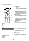
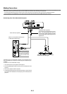
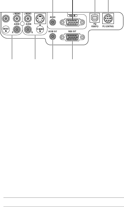
1. RGB IN / Component Input Connector (Mini D-Sub 15 Pin)
Connect your computer or other analog RGB equipment such as IBM
compatible or Macintosh computers. Use the supplied RGB cable to
connect to your computer. This also serves as a component input
connector that allows you to connect a component video output of
component equipment such as a DVD player. This connector also
supports SCART output signal. See page E-14 for more details.
2. RGB AUDIO Input Mini Jack (Stereo Mini)
This is where you connect the audio output from your computer or
DVD player when connected to the RGB input. A commercially avail-
able audio cable is required.
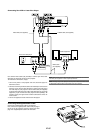
3. RGB OUT Connector (Mini D-Sub 15 Pin)
You can use this connector to loop your computer image to an exter-
nal monitor from the RGB input source.
This connector outputs RGB signal in standby mode.
4. AUDIO OUT Mini Jack (Stereo Mini)
You can use this jack to output sound from the currently selected
source (RGB, VIDEO or S-VIDEO). Output sound level can be ad-
justed in accordance with the sound level of the internal speaker.
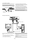
5. S-VIDEO IN Connector (Mini DIN 4 Pin)
Here is where you connect the S-Video input from an external source
like a VCR.
NOTE: S-Video provides more vivid color and higher resolution than the tra-
ditional composite video format.
S-VIDEO AUDIO Input Jacks R/L (RCA)
These are your left and right channel audio inputs for stereo sound
from an S-Video source.
6. VIDEO IN Connector (RCA)
Connect a VCR, DVD player, laser disc player, or document camera
here to project video.
VIDEO AUDIO Input Jacks R/L (RCA)
These are your left and right channel audio inputs for stereo sound
from a Video source.
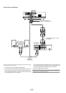
7. USB (PC) Port (Type B)
Connect this port to the USB port (type A) of your PC using the sup-
plied USB cable. You can operate your computer's mouse functions
from the remote control.
8. PC CONTROL Port (DIN 8 Pin)
For service personnel only.
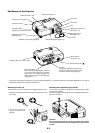
Terminal Panel Features
712 8
3456