


NetComm NCT240 Installation Guide Release 1.0
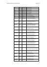
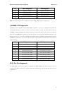
Pin MDI-X Assignment MDI Assignment
1
Input Receive Data + Output Transmit Data +
2
Input Receive Data - Output Transmit Data -
3
Output Transmit Data + Input Receive Data +
6
Output Transmit Data - Input Receive Data -
Note: Auto-negotiation must be enabled for automatic MDI/MDI-X pinout configuration.
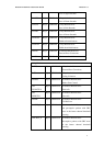
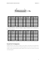
1000BASE-T Pin Assignments
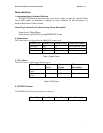
1000BASE-T ports support automatic MDI/MDI-X operation, so you can use straight-through cables for
all network connections to PCs or servers, or to other switches or hubs. The table below shows the
1000BASE-T MDI and MDI-X port pinouts. These ports require that all four pairs of wires be connected.
Note that for 1000BASE-T operation, all four pairs of wires are used for both transmit and receive. Use
100-ohm Category 5, 5e or better unshielded twisted-pair (UTP) or shielded twisted-pair (STP) cable for
1000BASE-T connections. Also be sure that the length of any twisted-pair connection does not exceed 100
meters (328 feet).
Pin MDI Signal Name MDI-X Signal Name
1
Transmit Data plus (TD1+) Transmit Data plus (TD2 +)
2
Receive Data minus (RD1-) Receive Data minus (RD2-)
3
Transmit Data plus (TD2+) Transmit Data plus (TD1+)
4
Transmit Data plus (TD3+) Transmit Data plus (TD4+)
5
Receive Data minus (RD3-) Receive Data minus (RD4-)
6
Receive Data minus (RD2-) Receive Data minus (RD1-)
7
Transmit Data plus (TD4+) Transmit Data plus (TD3+)
8
Receive Data minus (RD4-) Receive Data minus (RD3-)
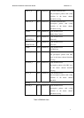
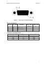
RJ-21 Port Pin Assignments
The PBX/MDF connector is designed to aggregate 24 POTS/ISDN ports. Each wire pair must be
attached to the RJ-21 connector in a specific orientation detailed below. The following table shows the pin
assignments.
29