


NetComm NCT240 Installation Guide Release 1.0
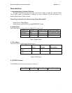
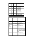
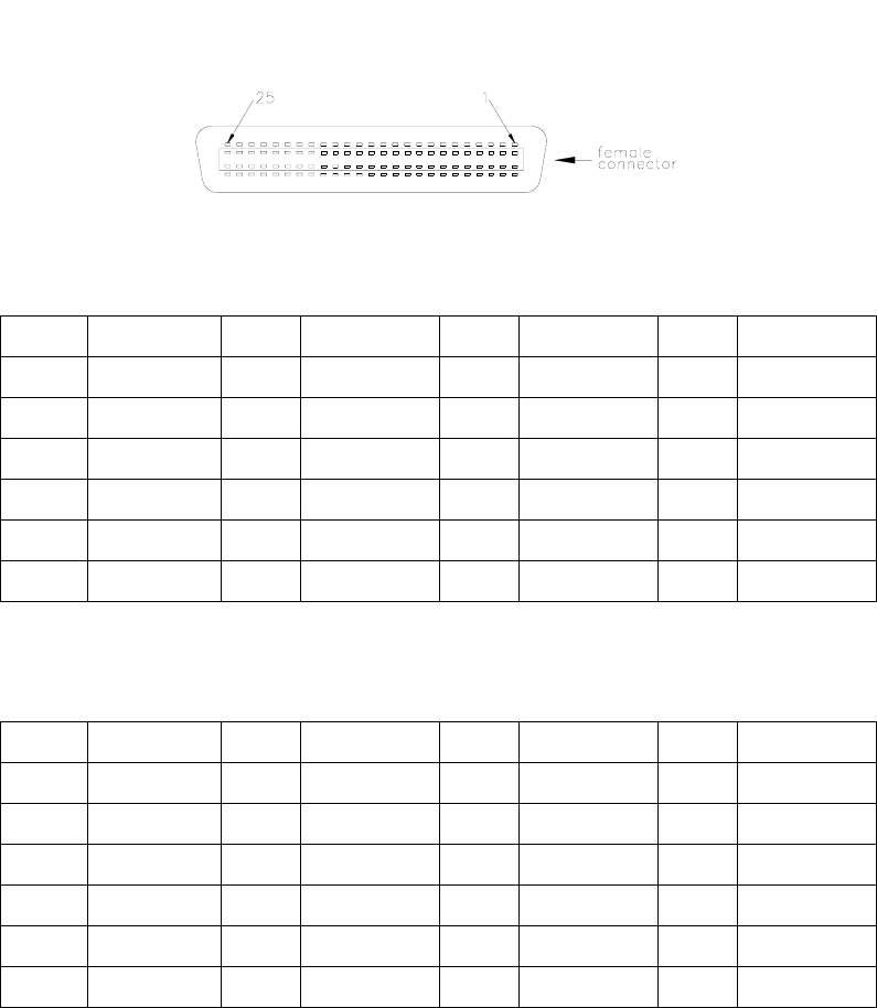
Pins Circuit Pins Circuit Pins Circuit Pins Circuit
1,26 1,Ring/Tip 7,32 7,Ring/Tip 13,38 13,Ring/Tip 19,44 19,Ring/Tip
2,27 2,Ring/Tip 8,33 8,Ring/Tip 14,39 14,Ring/Tip 20,45 20,Ring/Tip
3,28 3,Ring/Tip 9,34 9,Ring/Tip 15,40 15,Ring/Tip 21,46 21,Ring/Tip
4,29 4,Ring/Tip 10,35 10,Ring/Tip 16,41 16,Ring/Tip 22,47 22,Ring/Tip
5,30 5,Ring/Tip 11,36 11,Ring/Tip 17,42 17,Ring/Tip 23,28 23,Ring/Tip
6,31 6,Ring/Tip 12,37 12,Ring/Tip 18,43 18,Ring/Tip 24,49 24,Ring/Tip
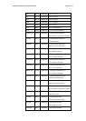
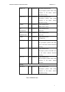
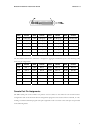
The Extended Ethernet Line connector is designed to aggregate 24 Ethernet ports. The following table
shows the pin assignments.
Pins Circuit Pins Circuit Pins Circuit Pins Circuit
1,26 Port 1 7,32 Port 7 13,38 Port 13 19,44 Port 19
2,27 Port 2 8,33 Port 8 14,39 Port 14 20,45 Port 20
3,28 Port 3 9,34 Port 9 15,40 Port 15 21,46 Port 21
4,29 Port 4 10,35 Port 10 16,41 Port 16 22,47 Port 22
5,30 Port 5 11,36 Port 11 17,42 Port 17 23,28 Port 23
6,31 Port 6 12,37 Port 12 18,43 Port 18 24,49 Port 24
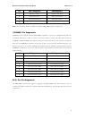
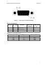
Console Port Pin Assignments
The DB-9 serial port on the switch’s rear panel is used to connect to the switch for out-of-band console
configuration. The on-board menu-driven configuration program can be accessed from a terminal, or a PC
running a terminal emulation program. The pin assignments used to connect to the serial port are provided
in the following tables.
30