Getting Started
7
NETGEAR ReadyDATA 5200
Rear Panel
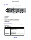
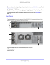
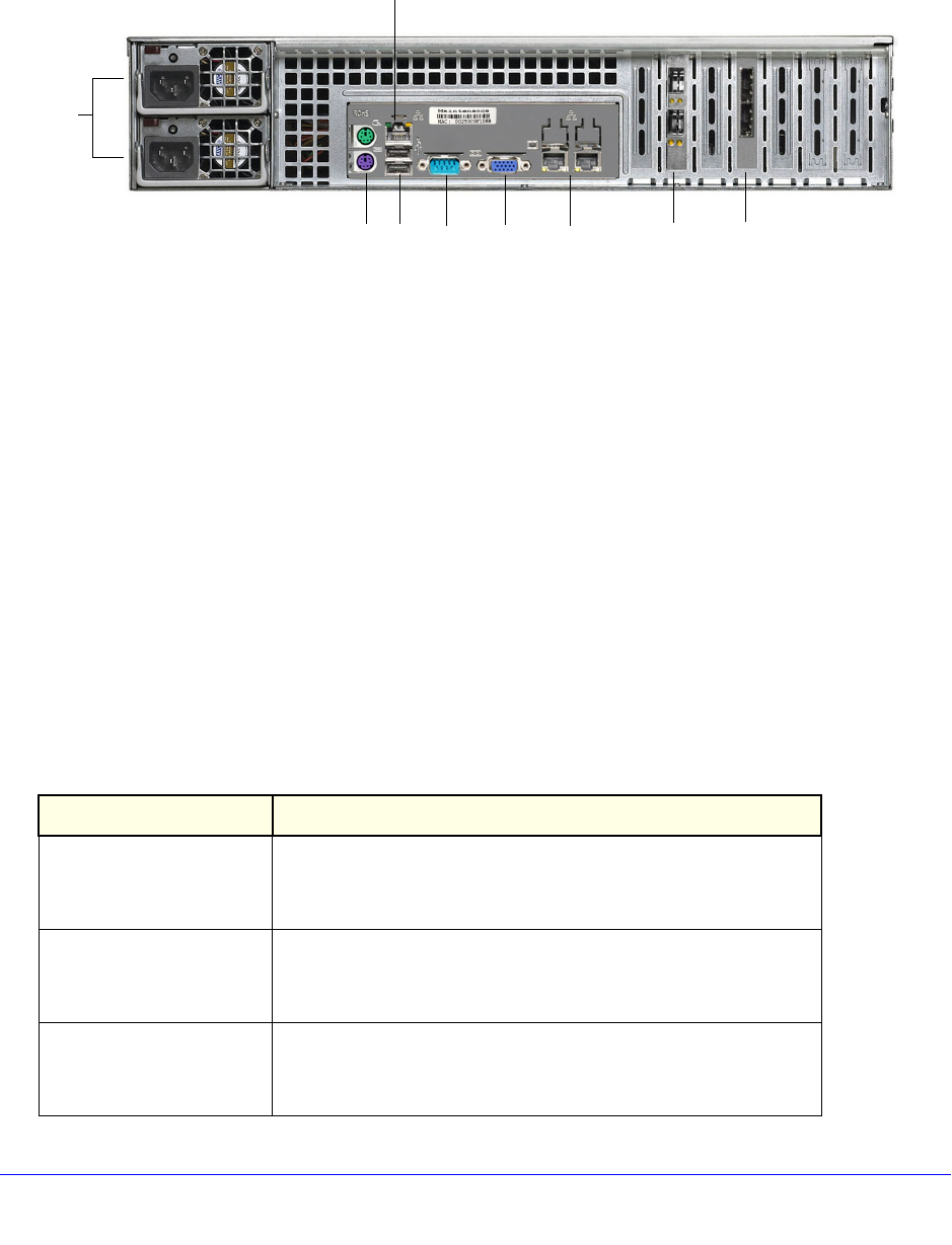
The following figure shows the rear panel of the ReadyDATA 5200.
1
2
3 4
5
6
7
8
9
Figure 5. ReadyDATA 5200 rear panel
1. Power supplies
2. PS2 keyboard and mouse ports
3. USB ports
4. RS232 console port
5. VGA monitor port
6. 1-gigabit Ethernet ports with status LED status indicators
7. 10-gigabit Ethernet ports with status LED status indicators
8. SAS output port
9. Maintenance port
Status and Shutdown
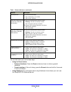
You can obtain information about the status of your unit by reviewing the indicators listed in
the following table.
Table 1. Status indicators
Indicator Description
Power LED The LED has these states:
• On. T
he unit is powered on.
• Off. T
he unit is powered off.
Disk activity LED The LED has these states:
• On
. A disk is active.
• Off. No disk is
active.
Power diagnostic LED The LED has these states:
• On
. Power failure
• Off. No
rmal operation


