Model FS516/FS524 Fast Ethernet Switch Installation Guide
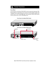
LEDs
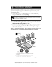
The table below describes the activity of the LEDs.
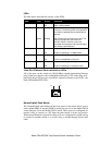
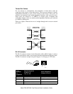
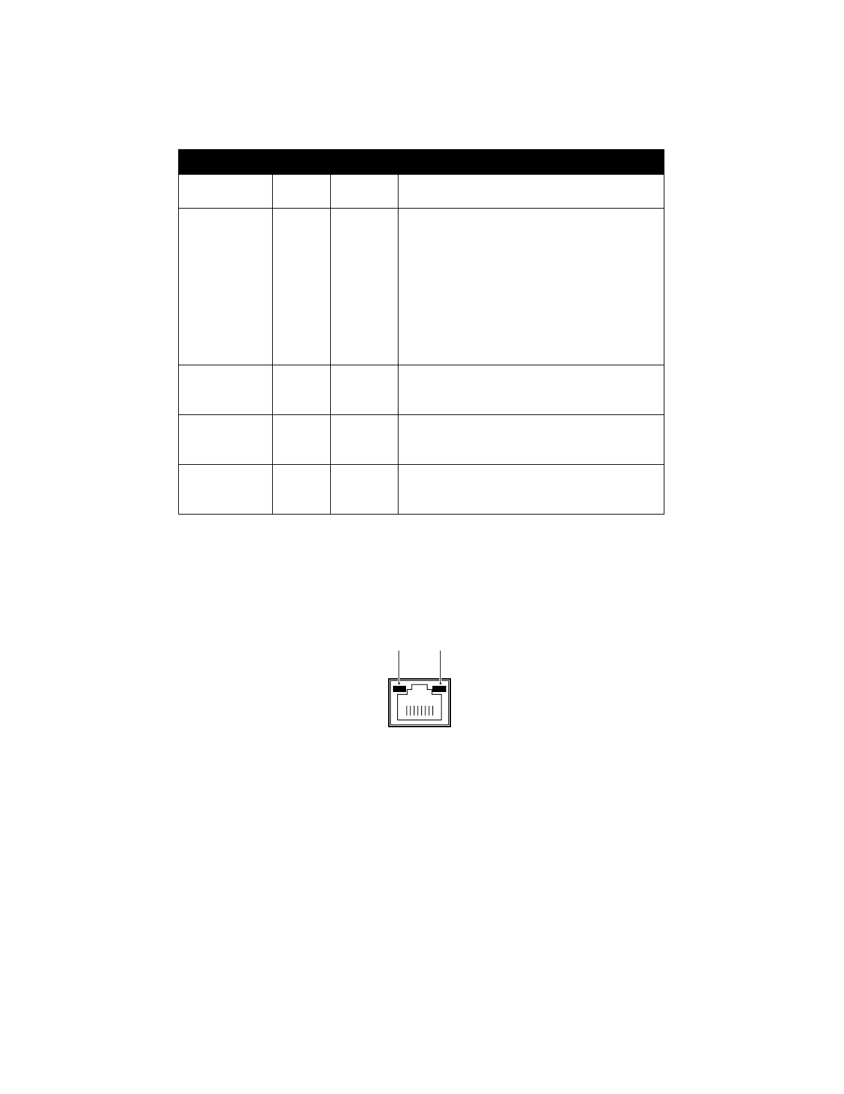
Vista RJ-45 Network Ports with Built-in LEDs
All of the ports on the switch are 10/100 Mbps capable autosensing Ethernet
ports. Each port supports only unshielded twisted pair (UTP) cable using an 8-
pin RJ-45 plug. Each port uses vista RJ-45 connectors that have two LEDs—the
Link LED and the FDX LED.
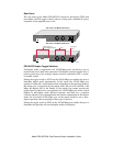
Normal/Uplink Push Button
The Normal/Uplink push button on the front panel of the switch allows you to
select uplink (MDI) or normal (MDI-X) wiring for port 16 on the Model FS516
switch and port 24 on the Model FS524 switch. These ports are configured for
normal wiring to connect to a PC when the push button is in the out position.
When the push button is pressed in, these ports are configured for uplink wiring
to connect to another switch or to a hub, using a straight-through twisted pair
cable.
Label Color Activity Description
Pwr (Power) Green On
Off
Power is supplied to the switch.
Power is disconnected.
Rx/Tx/Collision Green
Ye l lo w
Blinking
Blinking
Packet transmission or reception is occurring
on the port. The blinking action corresponds to
the number of packets that are transmitted or
received.
Data collisions are occurring on the port. The
blinking corresponds to the number of
collisions. When a collision occurs, the
connected device pauses and transmits again
after waiting a specified time.
100 Mbps Green On
Off
The port is operating in 100 Mbps mode.
The port is operating in 10 Mbps mode.
Link Green On
Off
A valid link is established on the port.
A link is not established on the port.
FDX Green On
Off
The port is operating in full-duplex mode.
The port is operating in half-duplex mode.
8923EB
Link
FDX


