


installation 4-4
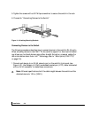
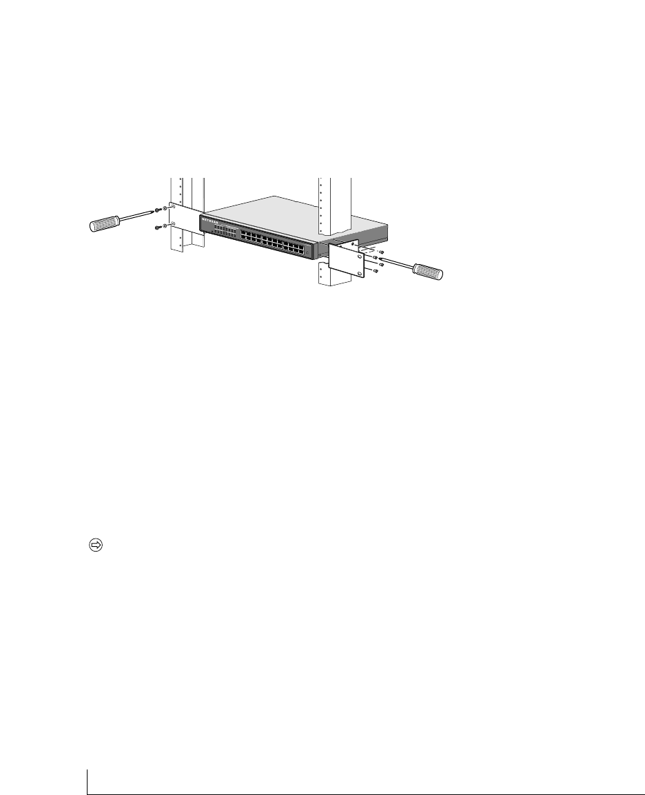
5.Tighten the screws with a #2 Phillips screwdriver to secure the switch in the rack.
6. Proceed to “Connecting Devices to the Switch.”
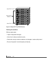
Figure 4-1.Attaching Mounting Brackets
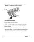
Connecting Devices to the Switch
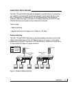
The following procedure describes how to connect devices to the switch’s RJ-45 ports.
When attaching devices to the FS517TS, the switch’s support for Auto Uplink technol-
ogy allows you to attach devices using either straight-through or crossover cables (for
more information about Auto Link
TM
technology, refer to “Auto Uplink (FS517TS)”
on page 2-5).
1.Connect each device to an RJ-45 network port on the switch’s front panel (see
Figure 4-2). Use Category 5 (Cat5) unshielded twisted-pair (UTP) cable terminated
with an RJ-45 connector to make these connections.
Note: Ethernet specifications limit the cable length between the switch and the
attached device to 100 m (328 ft).
M
O
D
E
L