


GS716T/GS724T Hardware Installation Guide
Physical Description 2-7
v1.0, January 2011
• System LEDs
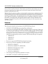
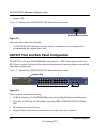
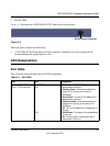
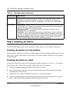
Figure 2-4 illustrates the NETGEAR GS724T Smart Switch back panel:
The back panel contains the following:
• A 100-240VAC/50-60 Hz universal input, which is a standard AC power receptacle for
accommodating the supplied power cord.
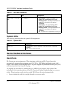
LED Designations
Port LEDs
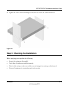
The following table describes the port LED designations.
Figure 2-4
Table 2-1. Port LEDs
Port LED Designation
16/24-10/100/1000 Mbps
Ports - 3 LEDs per port
LINK/ACT
SPD
FDX
• Solid Green - A valid 1000 Mbps link is
established on the port.
• Flashing Green - Packet transmission or
reception is occurring on the port at
1000 Mbps.
• Solid Yellow - A valid 10/100 Mbps link is
established on the port.
• Flashing Yellow - Packet transmission or
reception is occurring on the port at 10/
100 Mbps.
• Off - No 10/100 Mbps link is established on
the port.
• Solid Green - Full-duplex link is established
on the port.
• Off - No full-duplex or half-duplex link is
established on the port.
RS-232 Power Connector