


Reference Guide for the Model XM128 ISDN Digital Modem
E-2 Connector Pin Assignments
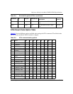
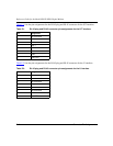
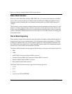
Table E-1 lists the pin assignments for the RJ-45 plug and RJ-45 connector for the S/T interface.
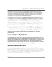
Table E-2
lists the pin assignments for the RJ-45 plug and RJ-45 connector for the U interface.
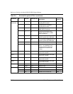
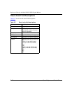
Table E-1. RJ-45 plug and RJ-45 connector pin assignments for the S/T interface
Pin Assignment
1 Not connected
2 Not connected
3 RCV +
4XMT +
5XMT -
6 RCV -
7 - 48V
8 - 48V RTN
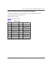
Table E-2. RJ-45 plug and RJ-45 connector pin assignments for the U interface
Pin Assignment
1 Not connected
2 Not connected
3 Not connected
4Ring
5Tip
6 Not connected
7 - 48V
8 - 48V RTN