


NTI NODEMUX MULTI-USER UNIVERSAL KVM SWITCH
20
RS232 CONTROL
Remote Connection
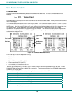
The RS232 Interface is designed to meet the RS232C standard and can be controlled from any CPU or other controller with an
RS232 communications port. The pin outs for the DB9 connector on the unit are as follows:
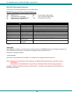
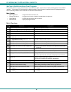
RS232 Connector (DB9 FEMALE)
PIN SIGNAL FUNCTION
1
None no connection
2 TXD Transmit Data (RXD at host)
3 RXD Receive Data (TXD at host)
4 DSR Data Set Ready
5 GND Signal Ground
6 DTR Data Terminal Ready
7 CTS Clear to Send
8 RTS Request to Send
9
none no connection
NOTE: Security must be disabled (see Administration Options on page 14) or user access granted (see System Access
List on page 15) on the port(s) to be selected by RS-232 control.
On the DB-9 female connector, pins 1 (DCD), 4 (DTR), and 6 (DSR) are shorted and pins 7 (RTS) and 8 (CTS) are shorted.
Therefore, CPU handshaking is bypassed and TXD and RXD are the only active signals. A straight through DB9 cable (not null
modem) will work for most CPUs. To daisy chain multiple units, the CPU drives the input port on the first unit and the output port is
connected to the input port on the next unit etc. The last unit will have a loop back plug installed in its RS232 OUT connector.
Baud Rate
The baud rate can be changed by selecting MENU on the front panel keypad. Then select 1 for SET BAUD RATE and select the
desired baud rate of 9600, 4800, 2400 or 1200. A data protocol of 8 data bits, no parity, and 1 stop bit is used for
communications.
Unit Address and Loop Back
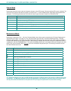
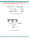
To allow multiple units to be controlled from a single CPU port, the RS232 control interface is designed to allow "daisy chaining"
up to 15 units. By setting the appropriate unit address with the keypad, each unit can be given a unique address (1-15). Then the
unit will only respond to commands on the bus if its address is embedded in the command.
To set the unit address using the front panel keypad,
1. Press <MENU>
2. press <2> for “SET UNIT ADDRESS“
3. enter the address number (1-15)
4. press <ENTER>.
The "loop back" plug should be on the RS232 OUT connector on the last unit in the chain. If only one unit is being controlled, the
loop back plug should be on the RS232 OUT connector on that unit.
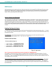
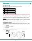
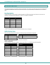
Figure 14- RS232 connection with "IN" and "OUT" ports
RS232
Serial
Port
RS232
IN
RS232
OUT
NTI
SWITCH
Unit Address 1
RS232
IN
RS232
OUT
NTI
SWITCH
Unit Address 2
RS232
IN
RS232
OUT
NTI
SWITCH
Unit Address 15
Loop back
Plug installed
Host
CPU