


NTI UNIMUX SERIES USB KVM SWITCH
12
RS232 CONTROL
(Optional)
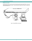
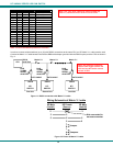
RS232 enables the UNIMUX to be remotely controlled via RS232. To control the UNIMUX via RS232 the user has three options:
• write a program that runs on a PC using the Command Protocol (page 14)
• use the NTI Switch Control Program (page 15) provided on the CD
• use the SerTest program (page 15) provided on the CD
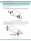
RS232 Connections and Configuration
Remote Connection
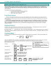
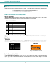
The RS232 Interface (optional) is designed to meet the RS232C standard and can be controlled from any CPU or other controller
with an RS232 communications port. The pin-out for the RJ45 connector on the unit is as follows:
RS232 (RJ45) CONNECTOR
PIN SIGNAL FUNCTION
1 - No connection
2 - No connection
3 RX+ Receive data (TXD at host)
4 GND Ground
5 - No connection
6 TX+ Transmit data (RXD at host)
7 - No connection
8 - No connection
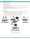
A 5 foot patch cable and two adapters, RJ45-to-DB9 and RJ45-to-DB25, have been provided for connection to most CPUs (see
page 7).
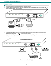
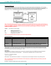
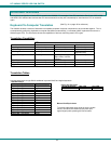
Baud Rate
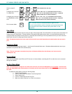
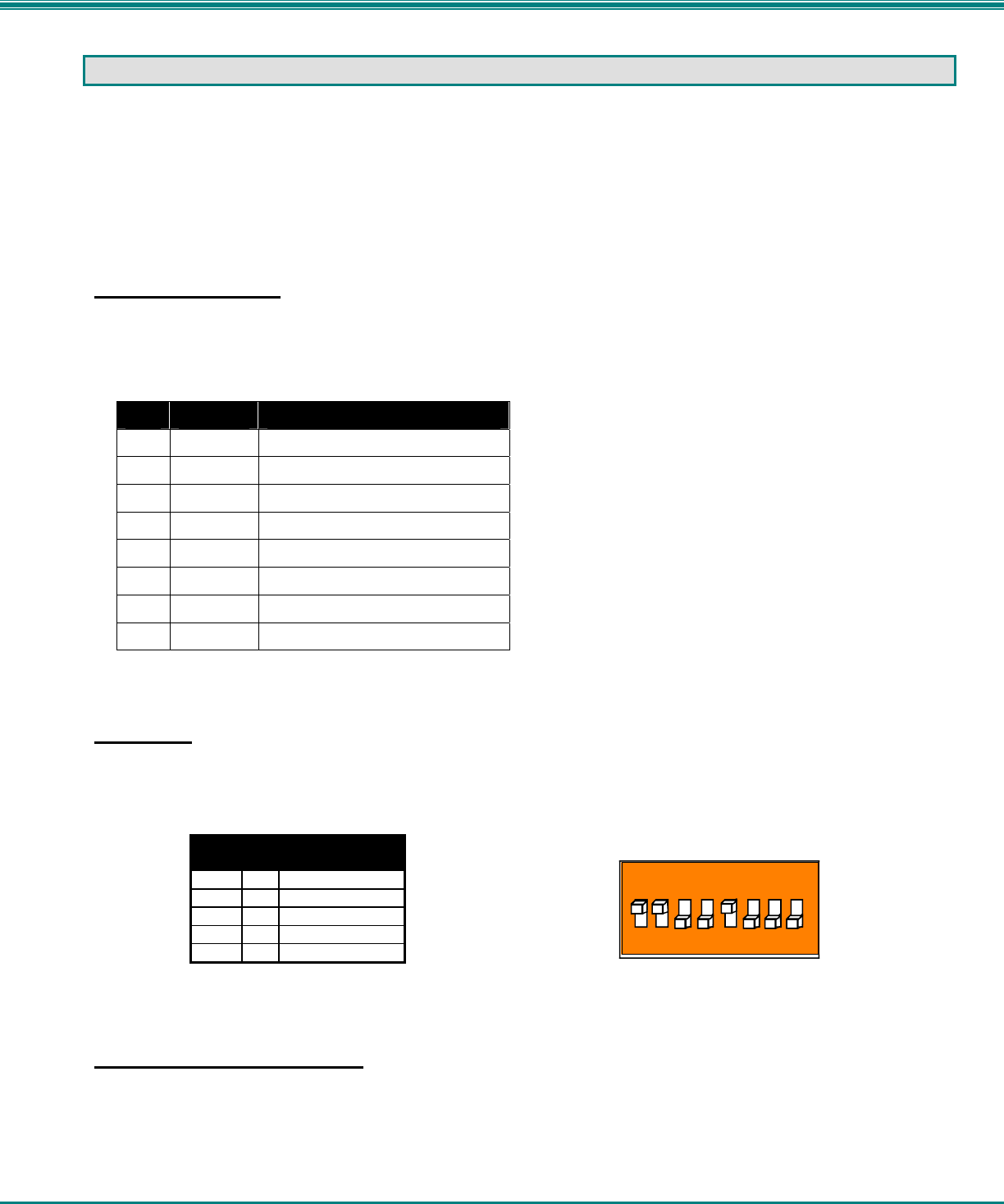
The baud rate can be changed by powering down the unit, changing the 8 position RS232 dip switch on the front of the UNIMUX,
and then powering back up. This table shows how to set the baud rate. (Fig. 10 shows switches in their factory default position.)
DIP
SWITCH
BAUD RATE
3 2
OFF OFF 2400
OFF ON 9600 (default)
ON OFF 19200
ON ON 38400
Figure 10- RS232 dip-switches
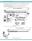
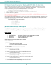
Unit Address and Loop Back
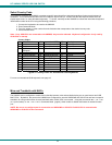
To allow multiple units to be controlled from a single CPU serial port, the RS232 control interface is designed to allow "daisy
chaining" up to 15 units. By setting the appropriate RS232 dip switches, each unit can be given a unique address (1-15). Then the
unit will only respond to commands on the bus if its address is embedded in the command. Use the following table to set the unit
address.
RS232
1
8
ON