


NTI UNIMUX SERIES USB KVM SWITCH
6
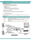
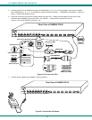
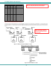
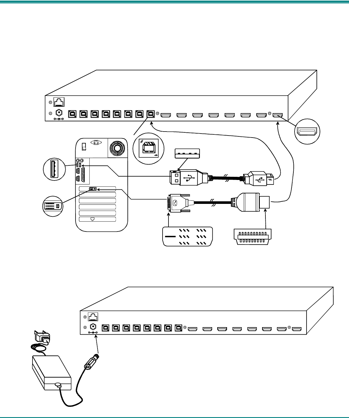
5. Connect each CPU to the USB switch using a DVI-HDMI-MM-x (x=3, 6, 10, or 15 foot) cable for each video connection
and a USB-AB-yM (y= .5, 1, 2, 3, or 5 meters) for each input device connection – REQUIRED (not supplied). (See Fig. 5
below.) Cables are available from NTI.
6. Group the input device and monitor interface cables from each CPU, making sure that cables from the first CPU are
connected to the UNIMUX at connectors CPU 1 and VIDEO 1. Cables from the second CPU should
connect to CPU 2 and VIDEO 2 connectors...etc.
Figure 5- Connect each CPU
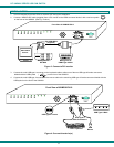
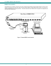
7. Connect the AC adapter to the UNIMUX. (See Fig. 6 below.)
Figure 6- Connect the AC adapter
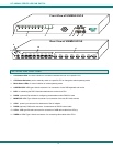
Rear View of UNIMUX-DVI-8
-
+
CPU 1CPU 2CPU 3CPU 4CPU 5CPU 6CPU 7CPU 8
VIDEO 1VIDEO 2VIDEO 3VIDEO 4VIDEO 5VIDEO 6VIDEO 7VIDEO 8
RS232
5VDC
USB Type B
Female
USB Type A Female
USB Type A Male
DVI Female
Video Connector
Rear View of Windows USB CPU
Video Port
Input Device Port
HDMI Type A
Video Connector
Mating Face of
DVI Male
Mating Face of
HDMI Type A Male
DVI-HDMI-MM-x
USB-AB-xM
5 VDC
AC
ADAPTER
Rear View of UNIMUX-DVI-8
-
+
CPU 1CPU 2CPU 3CPU 4CPU 5CPU 6CPU 7CPU 8
VIDEO 1VIDEO 2VIDEO 3VIDEO 4VIDEO 5VIDEO 6VIDEO 7VIDEO 8
RS232
5VDC