34 Chapter 2 Calculating transmission distance
212257-B
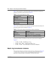
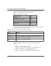
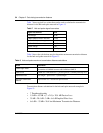
Table 7 shows typical loss values that can be used to calculate the transmission
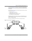
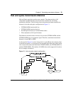
distance for the hub and spoke network in Figure 13.
Table 8 shows the calculations used to determine maximum transmission distance
for the hub and spoke network in Figure 13.
Transmission distance calculation for the hub and spoke network example in
Figure 13:
•
•
•
•
Table 7 Hub and spoke signal loss values
Signal loss element value
Loss budget 30 dB
CWDM OADM insertion add loss 1.9 dB
CWDM OADM passthrough loss 2.0 dB
CWDM OMUX8 demux loss 4.5 dB
System margin 3 dB
Fiber attenuation .25 dB per km
Table 8 Hub and spoke maximum transmission distance calculations
Result Calculation
Passthrough nodes
Passive loss
Implied fiber loss
Maximum transmission
distance
the number of OADMs between add OADM and OMUX
OADM add OMUX8 demux passthrough nodes OADM passthrough loss×()++
loss budget passive loss system margin––
implied fiber loss attenuation per kilometer
÷
7 Passthrough nodes
1.9 dB 4.5 dB+ 7 2.0×()20.4 dB Passive Loss=+
30 dB 20.4 dB – 3 dB– 6.6 dB Implied Fiber Loss=
6.6 dB .25 dB 26.4 km Maximum Transmission Distance=÷


