


Preinstallation requirements Standard 1.0
32 CallPilot
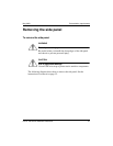
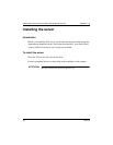
Note: The illustration shows a customer-supplied padlock (A).
1 If a padlock is installed on the back of the system, unlock and remove it.
Refer to “A” in the illustration.
2 Remove and save the three screws from the back of the side cover. Refer
to “B” in the illustration.
Note: You need the screws to reattach the side cover.
3 Place the fingertips of your left hand under the built-in handle on the back
of the cover.
4 Pull the cover approximately 2.5 cm (1 in.) away from the front of the
server until it stops. Refer to “C” in the illustration.
G100825
C
A
B
Bottom
tabs of
cover
Bottom
slots of
chassis