


1001rp server description Standard 1.0
14 CallPilot
Slot assignments
Introduction
The slot assignment tables show the following:
the physical location of boards inside the server, relative to other boards
the order in which boards are installed (for example, board #1, 2, 3, and
so on)
how the boards are represented in some CallPilot Manager applications
(such as the Maintenance Administration page)
the maximum capacity for each switch connectivity
Note: Your server may vary depending on what was ordered from Nortel
Networks. Therefore, your server may not have all of the slots populated.
Slot definition and slot numbering
In these tables, the term “slot” refers to the available slot openings in the
chassis, not the PCI or ISA connectors inside the server.
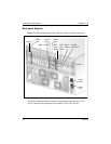
Look at the server from the rear (see “Rear panel diagram” on page 12). The
slots are numbered from right to left, 1 to 20. Now, look at the server from
the front. The slots are numbered from left to right.
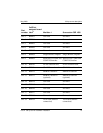
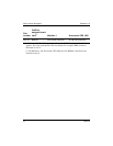
1001rp slot assignments
Slot
number
CallPilot-
assigned board
label
a
Meridian 1 Succession CSE 1000
Slot 1 BRD01 Not used Not used
Slot 2 BRD02 Not used Not used