


Nautica 200 Installation Guide
117236-B Rev. 00 7
1. Connect one end of the black ISDN cable (labelled
119071-A) or the red ISDN cable (labelled 117238) to the
ISDN port on the back of the Nautica 200. Then, connect
the other end of the cable to the ISDN wall outlet.
In North America, instead of the ISDN cables mentioned
in point one, you may have an RJ-45 to RJ-11 cable
(labelled 119068-A) instead. Connect the RJ-45 end of
this cable into the back of the Nautica 200 and the RJ-11
end of the same cable into the ISDN wall outlet.
2. Connect one end of the gray LAN cable (labelled 118314)
to the LAN port. Then, connect the other end of the cable
to the NIC on the back of your PC.
3. Connect one telephony device (telephone, facsimile or
modem) to each telephone port. If you are in the UK, you
must use the telephone adapters supplied with your
Nautica 200. In other countries, you may need to supply
your own telephone adapters.
4. Connect the power cable to the port labelled 9v DC. The
Nautica 200 has no on/off switch; it turns on immediately
when you plug the power adapter into the power outlet.
5. The Manager port is used for troubleshooting only. The
Manager cable is labelled 117239. Connect this cable only
if you are an experienced user of Nautica products and
you want to start a local management session with the
Bay Command Console (BCC
™
).
Note:
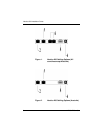
If you are iunstalling the Australian version (see Figure
2), ignore step 3 and proceed to step 4.
Warning:
Disconnect the ISDN cable from the wall outlet
before connecting it to or disconnecting it from the Nautica 200.