


Chapter 1 Passport 8600 modules 37
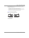
Installing Passport 8600 Switch Modules
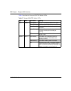
The Passport 8683POSE Module has an Online LED that indicates overall status
for the module. Table 10 describes the Online LED.
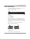
Passport 8691SF Module
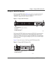
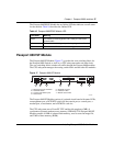
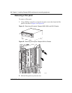
The Passport 8691SF Module (Figure 17) provides the core switching fabric for
the Passport 8600 Switch, as well as a a CPU subsystem and a real-time clock.
The core switching fabric switches all traffic through the Passport 8600 modules.
The CPU subsystem manages the routing switch fabric and the other I/O modules.
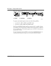
Figure 17 Passport 8691SF Module
The Passport 8691SF Module consists of a printed circuit board with status LEDs,
a management port, a DCE/DTE switch for the console port, a console port, a
modem port, a reset button, and a PCMCIA card slot.
The CPU subsystem uses a PowerPC CPU and has 64 megabytes (MB) of
synchronous dynamic random access memory (SDRAM). The Passport 8691SF
Module contains 16 MB of onboard flash memory, used to store the image file,
and 2 MB of boot memory (ROM).
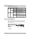
Table 10 Passport 8683POSE Module LED
Color/State Meaning
Green The module is receiving power and is ready to receive and
transmit traffic.
Amber The module is initializing and performing diagnostic self-tests.
Off The module is offline and is not receiving power.
10354EA
OnlineTemp2
Fan
1
MasterPower Supply100035 50 75
3
21
Modem (DTE)
PCMCIA
Utilization
Switch
CPU
Link
100
Reset
Console
DCE|DTE
Management
1
2 3 4 5 6
1 = Management port and LEDs
2 = DCE/DTE switch
3 = Console and Modem ports
4 = Reset button
5 = PCMCIA card slot
6 = Utilization LEDs
7 = Module status LEDs
7