


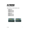
12/15/05
10
For 10/100 Base-TX ports, plug a Category 5 (or better) twisted pair
cable into one the RJ45 copper ports (1-6). Connect the other end to
the far end station. Verify that the Port LED’s are ON once the
connection has been completed. For Switch to Switch or Switch to
Repeater connections, a crossover cable may be required if the
connecting unit does not support the HP-MDIX auto cable detect
feature. For 10/100BaseTX operation, the 600 Series Switch will sense
& adapt accordingly.
A maximum number of 50 600 Series switches can be connected in a
single ring.
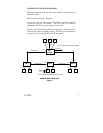
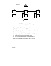
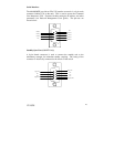
CONNECTING MULTIPLE RINGS (608MFX Only)
For multiple rings, the connection between two network segments is
made on two separate paths. Two of the 608MFX’s in a ring are
connected together via a connection cable with an ITP cable (maximum
length of 40m), and inform each other of their operating states. One of
the 608MFX units is assigned the redundant function using the DIP
switch setting “Stby on” (Standby Slave). The other 608MFX unit
takes over the function of the Standby Master, with the DIP switch
setting “Stby off” (see Figure 2). Please note that 604MFX units
cannot be used as Ring Couplers.
Because of the 50-unit ring limit, for larger networks, the user must
configure multiple rings. By using the Master/Slave Standby approach
to couple rings together, the user can enlarge the network by chaining
segments.
Port Assignment in the Standby Mode
On the Standby Master and Standby Slave only port #1 (default
standby port) can be used for the coupling to the neighboring ring.
Connect the #1 ports together using a CAT5E crossover cable between
switches. Ports 2-6 can be used just as normal switch ports.
Simultaneous Standby and Redundancy Manager Operation
A standby master or standby slave can adopt the function of a
redundancy manager at the same time.