


12/15/05
8
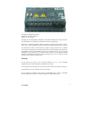
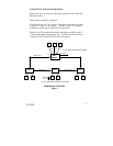
APPLYING POWER
1. Unscrew the flange & remove the DC Voltage Input Plug from the
Header.
2. Install the DC Power Cables into the Plug(s) (observing polarity
per the legend on the top of the unit). L1+ and L2+ are the +24V
connections. M1 and M2 are the minus (-) returns for the L1 and
L2 respectively. F1 and F2 terminals are across the contact switch
that opens to signify a fault detection. Voltage/Current for F1/F2
is limited to 24V @ 100mA.
3. Plug the Voltage Input Plug back into the side header. All LED’s
will flash ON Momentarily.
4. The unit will complete the power up cycle in approximately 20
seconds.
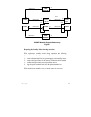
Note: Only 1 power supply is required to be connected to power for
minimal operation. For redundant power operation, L1 and L2
terminals must be connected to separate DC Voltage sources. Use wire
sizes 14-28 gauge.
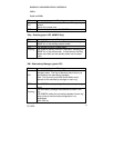
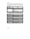
Recommended 24V DC Power Supplies, similar to:
100VAC/240VAC:
N-Tron’s NTPS-24-1.3, DC 24V/1.3A,
Operating temp range -10°C to +60°C