


12/15/05
9
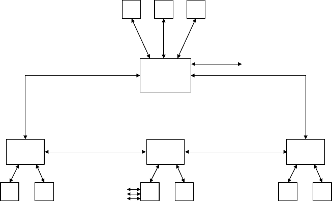
CONNECTING THE STANDARD RING
Remove the dust cap from the fiber optic connectors and connect the
fiber optic cables.
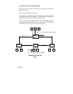
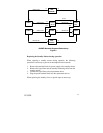
Please refer to the Figure 1. Diagram.
To begin the ring, the TX out-port #7 should be connected to the RX
in-port #8 of the far end station. The RX in-port #7 should be
connected to the TX out-port #8 on the far end station.
Likewise, the TX out-port #8 should be connected to the RX in-port #7
of the far end station completing the ring. The RX in-port #8 should be
connected to the TX out-port #7 on the far end station.
608MFX
RING
MANAGER
608MFX RING TOPOLOGY
Figure 1
608MFX 608MFX
PC
MMI
PC
MMI
PC
MMI
CAT5 TO MES
CAT5
CAT5
CAT5
FIBER OPTIC PAIR
FIBER OPTIC PAIR
FIBER OPTIC PAIR
PLC PC
LAPTOP
CAT5 CAT5
N-TRON
405TX
PLC
CAT5 CAT5
PLC DRIVE
CAT5 CAT5
(UP TO 6 COPPER PORTS CONNECTED TO 608MFX)
(UP TO 6 COPPER PORTS CONNECTED TO EACH 608MFX)
#7
#8
#7
#8
#7
#8
#7
#8
608MFX
Additional
Ports