


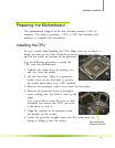

Hardware Installation
21
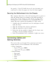
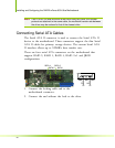
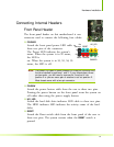
Connecting Internal Headers
Front Panel Header
The front panel header on this motherboard is one
connector used to connect the following four cables:
PWRLED
Attach the front panel power LED cable to
these two pins of the connector.
The Power LED indicates the system’s
status. When the system is in S0 status,
the LED is
on. When the system is in S1, S3, S4, S5
status, the LED is off.
Note: The power LED cable in some chassis is a three pin connector with
the pins installed in positions 1 and 3. If your chassis has a three
pin connector, you will need to remove pin 3 and put it into
position 2 or you can use a pair of scissors to cut out position 2.
Most chassis come with a two pin connector.
PWRSW
Attach the power button cable from the case to these two pins.
Pressing the power button on the front panel turns the system on
off rather than using the power supply button.
HD_LED
Attach the hard disk drive indicator LED cable to these two pins.
The HDD indicator LED indicates the activity status of the hard
disks.
RESET
Attach the Reset switch cable from the front panel of the case to
these two pins. The system restarts when the
RESET switch is
pressed.
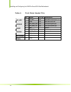
PWRSW - +
PWRLED
1
2
1
9
10
HD_LED
RESET - +
No
Connect
Blan
k