


Appendix
IN9 32X/IN9 32X-MAX 5-1
5. Appendix
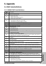
5.1 POST Code Definitions
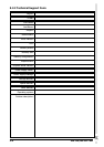
5.1.1 AWARD POST Code Definitions
POST
(hex)
Description
CF Test CMOS R/W functionality
C0
Early chipset initialization:
-Disable shadow RAM
-Disable L2 cache (socket 7 or below)
-Program basic chipset registers
C1
Detect memory
-Auto-detection of DRAM size, type and ECC
-Auto-detection of L2 cache (socket 7 or below)
C3 Expand compressed BIOS code to DRAM
C5 Call chipset hook to copy BIOS back to E000 & F000 shadow RAM
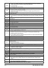
01 Expand the Xgroup codes locating in physical address 1000:0
03 Initial Superio_Early_Init switch
05
1. Blank out screen
2. Clear CMOS error flag
07
1. Clear 8042 interface
2. Initialize 8042 self-test
08
1. Test special keyboard controller for Winbond 977 series Super I/O chips
2. Enable keyboard interface
0A
1. Disable PS/2 mouse interface (optional)
2. Auto detect ports for keyboard & mouse followed by a port & interface swap (optional)
3. Reset keyboard for Winbond 977 series Super I/O chips
0E
Test F000h segment shadow to see whether it is R/W-able or not. If test fails, keep beeping
the speaker
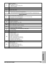
10
Auto detect flash type to load appropriate flash R/W codes into the run time area in F000 for
ESCD & DMI support
12
Use walking 1’s algorithm to check out interface in CMOS circuitry. Also set real-time clock
power status, and then check for override
14
Program chipset default values into chipset. Chipset default values are MODBINable by
OEM customers
16
Initial onboard clock generator if Early_Init_Onboard_Generator is defined. See also POST
26.
18 Detect CPU information including brand, SMI type (Cyrix or Intel) and CPU level (586 or 686)
1B
Initial interrupts vector table. If no special specified, all H/W interrupts are directed to
SPURIOUS_INT_HDLR & S/W interrupts to SPURIOUS_soft_HDLR.
1D Initial EARLY_PM_INIT switch
1F Load keyboard matrix (notebook platform)
21 HPM initialization (notebook platform)
23
1. Check validity of RTC value: e.g. a value of 5Ah is an invalid value for RTC minute.
2. Load CMOS settings into BIOS stack. If CMOS checksum fails, use default value instead.
24
Prepare BIOS resource map for PCI & PnP use. If ESCD is valid, take into consideration of
the ESCD’s legacy information.
25
Early PCI Initialization:
-Enumerate PCI bus number.
-Assign memory & I/O resource
-Search for a valid VGA device & VGA BIOS, and put it into C000:0