


Introduction
The OMS-820 is a companion module to the MOTM-820 voltage controlled lag processor. It
adds powerful new features to the superb Synthesis Technology module. No component
changes are needed to the MOTM module, and the two modules are connected together by
just one removable connector hidden behind the front panels.
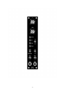
The module is designed to fit into a 1U MOTM style panel. It requires the standard MOTM or
Oakley power supply.
With this module you can make the MOTM-820 into a voltage controlled LFO with variable
waveshape. Or you use it to make a powerful voltage controlled envelope generator, with
manual set and preset modes. You will be amazed by the uses you can find for this module.
1. LFO
When the mode switch is turned to LFO, the output(s) of the MOTM module will oscillate
between +5V and -5V. The rise time of the waveform will be set by the UP control and the fall
time will set by the DOWN control. The frequency will change according to the settings of
both UP and DOWN. You can also change the rise and fall time together with the UP/DOWN
control on the MOTM. You can easily make saw, reverse saw, and triangle type waveforms.
The LIN/LOG pot on the MOTM will alter the shape of the waveform by introducing the
usual non-linearites of the exponential rise and decay.
Top frequency is 1KHz or so, whilst the lowest frequency is so low I got bored waiting for
one cycle.
2. EG mode
When the mode switch is turned to EG (envelope generator), you get a voltage controlled
AD/AR generator and more besides. This section has four sub-modes. These are selected by
two switches: AD/AR and Gated/Resetable.
The envelope generator can be triggered by two means, either a gate input as normal ADSRs,
or a push button, GATE, on the front of the OMS-820. When in AD (attack-decay) and Gated
mode, the output of the MOTM-820 will then rise until +5V is reached, whereupon it will fall
back to zero. Rise and fall times are governed by the MOTM-820 of course, and fully voltage
controlled. Removal of the gate signal will cause the decay phase to start prematurely.
Standard A-D EG behaviour.
Switch the unit to AR (attack-release) and gated mode, and the output will rise to +7V or so,
and stay there until the gate is released. Standard A-R EG behaviour.
For either of the above modes, pressing the RESET switch will start the decay or release
phase regardless of the gate's condition. The RESET input has no effect in this mode.
Switch to AD and Resetable mode. The MOTM output will now rise to a +5V peak when the
gate input goes high or the GATE switch is pushed. It will then fall back to zero
3