


automatically. Removing the gate has no effect on the output. This is 'one shot' mode.
However, the output may be forced to decay prematurely by pressing the RESET push button,
or by use of the RESET input. A positive signal of above 3V or so will activate reset.
Switch to AR and Resetable mode. The MOTM output will rise until +7V is reached whereby
it will stay there indefinitely, or until the RESET button or RESET input is activated.
Remember that all rise and fall times are controlled by the pots on the MOTM-820 and
OMS-820. And can be varied from less than 1mS to well over two minutes.
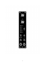
Four LEDs are included on the front panel. Two of these indicate the status of the gate and
reset inputs. Another will show the EG's status, this will light when the MOTM’s output is
rising or stationary. A fourth LED, a bicolour type, will give visual indication of the final
output signal.
The OMS-820's two pots together with the MOTM's own pots, control the rise and fall time.
This will enable you to set a time of say, 1 sec with the OMS-820's pots and then introduce a
modulation signal at the MOTM’s CV inputs. The depth of which is controlled by the
MOTM's pots.
The OMS-820 and the MOTM-820 are connected together by one 4 way 0.1" connector. It
can be simply removed if the modules need to come apart at anytime. The wires from the
connectors are simply soldered to special key locations on the MOTM-820. No component
changes are required to the MOTM-820 at all. Inserting a jack plug into the IN socket of the
MOTM will override any control signal sent by the OMS-820. The MOTM-820 will then
behave as a conventional VC Lag module.
Of Pots and Power
There are just two main control pots on the PCB. If you use the specified pots and brackets,
the PCB can be held firmly to the panel without any additional mounting procedures. The pot
spacing is on a 1.625” grid and is the same as the vertical spacing on the MOTM modular
synthesiser. The PCB has four mounting holes, one in each corner should you require
additional support which you probably won’t.
The design requires plus and minus 15V supplies. These should be adequately regulated. The
current consumption is about 20mA, although this varies slightly as the OUT LED turns on
and off. Power is routed onto the PCB by a four way 0.156” Molex type connector. Provision
is made for the two ground system as used on all Oakley modular projects, and is compatible
with the MOTM systems. See later for details.
Circuit Description
Let us first refresh ourselves with the operation of the MOTM-820. Basically it is a capacitor
that can discharged and charged at a controlled rate. The level to which the capacitor charges
to, or discharges to, is determined by the input voltage applied to the MOTM-820. The
4