


SAFETY NOTE: Disconnect all signal input and outputs before attempting this procedure.
Instructions
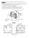
1) Open the Signal Conditioner Unit—Remove Side Covers from Unit by lifting at the “angled
corners” first, using a flat-head screwdriver. Continue detaching remaining edges of the Cover.
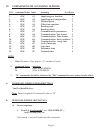
2) Short TP6 & TP17 together, either by wire or, if available, jumper S1-A.
3) After shorting TP6 to TP17, apply power to the unit.
4) The Front Panel Power Indicator (LED) will NOT
turn on.
5) After power has been applied to the unit for about 30 seconds, turn power off.
6) The communication parameters now have been restored to the default settings.
7) Use the DRX Set-up Program to establish communication with the meter.
8) This procedure will not affect calibration. It only resets the communication parameters.
Page 5
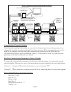
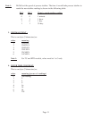
Solder wire from
TP6 to TP17 on
Solder side of Board.
Install Jumper onto
S1-A on Component
Side of Board.
Version A Version B
Testpoint/Jumper Locations
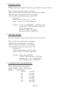
Lift Cover at Angled Corners.
Lift Cover at Angled Corners.
Front Panel
Side Cover
Remove to
Access S1-A
Jumper
Side Cover
Remove to
Access
Testpoints.
Six Attachments Per Side
Opening Unit