7.0 PCI-DAS1000 REGISTER DESCRIPTION
7.1 REGISTER OVERVIEW
PCI-DAS1000 operation registers are mapped into I/O address space. Unlike ISA bus designs, this board has
several
base
addresses each corresponding to a reserved block of addresses in I/O space. As we mention in our programming chapter,
we highly recommend customers use the Universal Library package. Direct register level programming should be attempted
only by extremely experienced register level programmers.
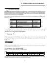
Of six Base Address Regions (BADR) available in the PCI 2.1 specification, five are implemented in this design and are
summarized as follows:
16-Bit WORDDAC Data RegistersBADR4
8-Bit BYTEPacer, Counter/Timer and DIO RegistersBADR3
16-Bit WORDADC Data, FIFO Clear RegistersBADR2
16-Bit WORDGeneral Control/Status RegistersBADR1
32-Bit DWORDPCI Controller Operation RegistersBADR0
OperationsFunctionI/O Region
BADRn will likely be different on different machines. Assigned by the PCI BIOS, these Base Address values cannot be
guaranteed to be the same even on subsequent power-on cycles of the same machine. All software must interrogate BADR0
at run-time with a READ_CONFIGURATION_WORD instruction to determine the BADRn values. Please see the "
1997
AMCC S5933 PCI Controller Data Book"
for more information.
7.2 BADR0
BADR0 is reserved for the AMCC S5933 PCI Controller operations. There is no reason to access this region of I/O space
for most PCI-DAS1000 users. The installation procedures and Universal Library access all required information in this
area. Unless you are writing direct register level software for the PCI-DAS1000, you will not need to be concerned with
BADR0 address.
7.3 BADR1
The I/O region defined by BADR1 contains 5 control and status registers for ADC, DAC, interrupt and Autocal operations.
This region supports 16-bit WORD operations.
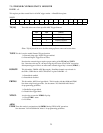
7.3.1 INTERRUPT / ADC FIFO REGISTER
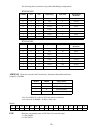
BADR1+ 0: Interrupt Control, ADC status. A read/write register.
WRITE
INT0INT1INTE-EOAIE-EOACLINTCL-----ADFLCL
-
-
0123456789101112131415
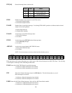
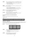
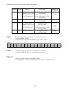
Write operations to this register allow the user to select interrupt sources, enable interrupts, clear interrupts as well as ADC
FIFO flags. The following is a description of
the Interrupt/ADC FIFO Register:
17


