


5
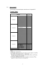
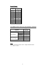
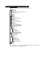
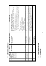
2.2. PIN LAY-OUT
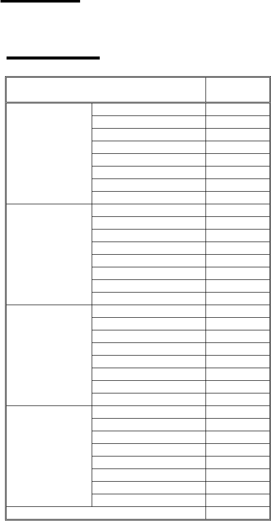
The drawings of the input/output connections are in Appendix B.
Encoder Inputs
Function
D-Type
44 pin No.
Vcc
31
Index+
17
GND
2
Index–
32
Sine– / Phase A–
18
Sine+ / Phase A+
3
Cosine+ / Phase B+
33
Encoder A
Cosine– / Phase B–
4
GND
20
Vcc
5
Index+
35
Sine+ / Phase A+
21
Index–
6
Sine– / Phase A–
36
Cosine– / Phase B–
22
Encoder B
Cosine+ / Phase B+
7
Vcc
23
GND
38
Index–
24
Index+
9
Sine+ / Phase A+
39
Cosine+ / Phase B+
25
Sine– / Phase A–
10
Encoder C
Cosine– / Phase B–
40
Vcc
41
Index+
27
GND
12
Index–
42
Sine– / Phase A–
28
Sine+ / Phase A+
13
Cosine+ / Phase B+
43
Encoder D
Cosine– / Phase B–
14
GND
30
Notes:
1. Total max. current 0.7A.
2. The inputs can be sine (sine and cosine) or square (phases A and B).
3. For single ended inputs use the ‘–’ input only.
The two non-connected wires per each encoder (Sine+ and Cosine+
should be floating, not grounded.
4. All the five GND pins (2, 20, 38, 12 and 30) are shortened. They
appear five times to make the wiring easier.