


3.2.1 Section 1
Although there are 128 I/O ports used by the on-board PCI interface
controller, only one register is used for most applications. The user should
not modify the other registers! The PCI interrupt control register (4Ch)
controls the interrupts generated by the system. The register is set to “disable
interrupt” after power-on or hardware reset signal, thus no interrupts will be
generated before this register is activated even if the user enables the add-on
interrupt! In order to enable the PCI-interrupt, write 43h to this register. Write
03h to this register if you want to disable the PCI interrupts.
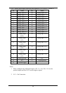
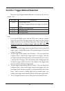
Following is the format of the PCI interrupt control register:
Bit 31-Bit 7 Bit6 Bit5-Bit3 Bit2 Bit1-Bit0
Not used Interrupt Enable Not used Interrupt Flag Interrupt Select
Bit 6: Write an ‘1’ to enable the PCI-interrupt and a ‘0’ to disable PCI interrupt.
Bit 2: This bit is read-only. A ‘1’ indicates that the Add-on has
generated an interrupt, ‘0’ means that Add-on did not generate an interrupt.
Bit1-0: Always write 1 to these two bits.
Note:
1. Since the OME-PCI-1002 supports “Plug and Play”, the interrupt
number will automatically be assigned by your system. The user can
determine the interrupt number by using standard PCI utilities or by
using the OME-PCI-1002 software driver.
2. If your system supports “Shared IRQ”, several peripherals may
share the same IRQ at the same time. You must use Bit-2 to find out
if an IRQ was generated from the OME-PCI-1002 or a different
device!
3. For more information about the PCI interrupt control, please refer to
the user reference manual of the PLX-9050.
29