


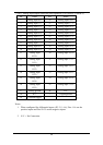
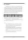


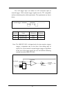

For OME-PCI-1002H:
[Bit1,Bit0] [0 0] [0 1] [1 0] [1 1]
Gain 1 10 100 1000
3. These registers are set to 0 after power-on or a hardware reset signal.
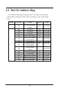
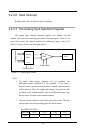
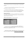
3.2.2.8 The General Control Register
The general control register (18h) is used to control the add-on interrupt
source and the A/D trigger method. The format of this register is:
Bit4-2 Bit 1-0
Interrupt source
selection register
A/D trigger method
selection register
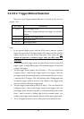
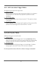
3.2.2.8.1 Interrupt Source Selection
There are four interrupt sources selectable for the OME-PCI-1002 (see
section 1.4.4).
[Bit4,Bit3,Bit2] Description
[ 0, 0, 0 ] No interrupt source, disable all interrupts.
[ 0, 0, 1 ] Interrupt after A/D conversion completes.
[ 0, 1, 0 ] Interrupt after 8254 timer 0 falling.
[ 0, 1, 1 ] Interrupt after external trigger falling.
[ 1, 0, 0 ] Interrupt after 8254 timer 1 falling.
Others No interrupt source, disable all interrupts.
Note: Bit 3-3 of general control register is set to 0 after a hardware reset.
33