


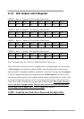
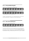
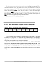
2.4.4 D/I Input Buffer Register
(READ) Base+6 : D/I Input Buffer Low Byte Data Format
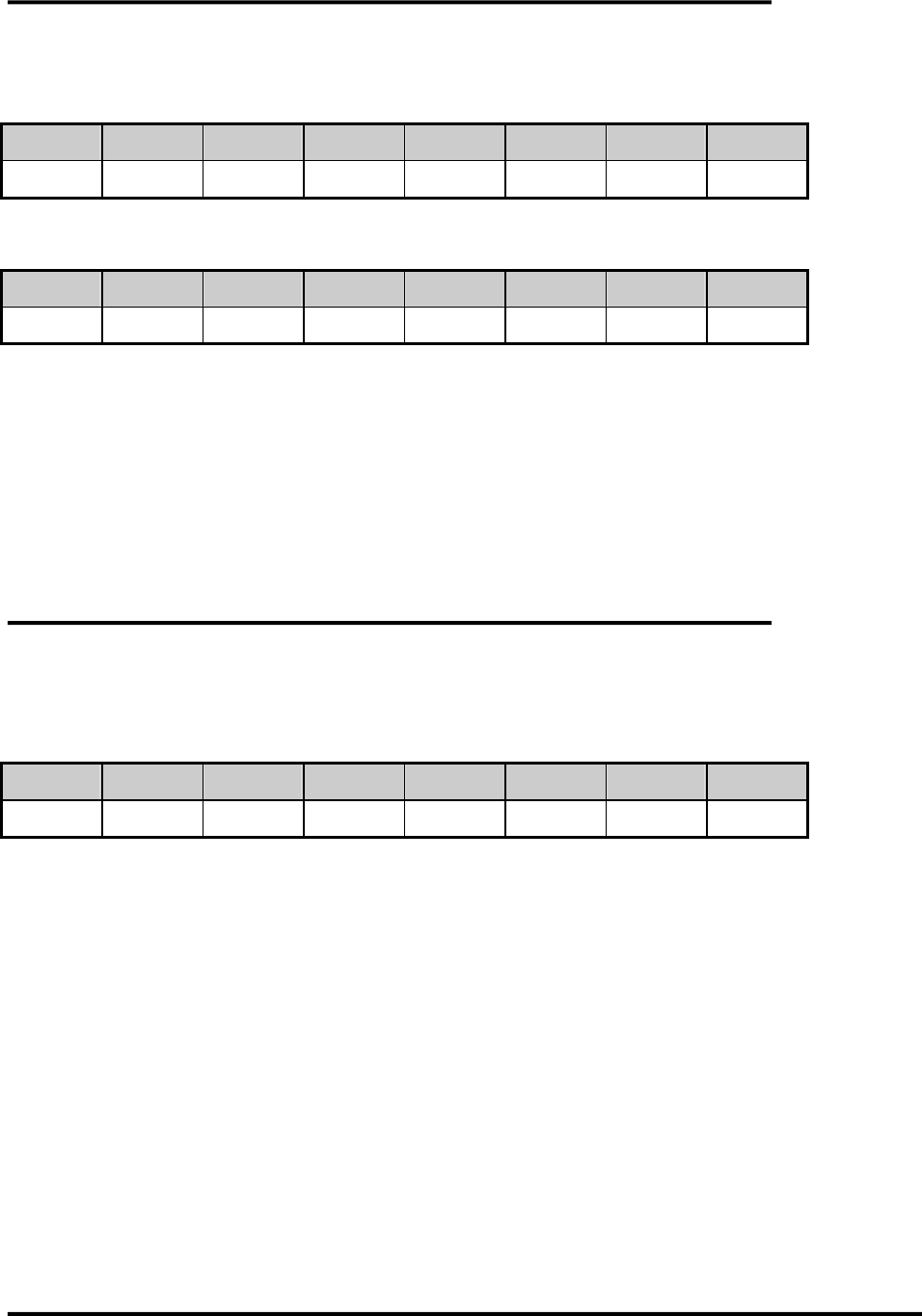
Bit 7 Bit 6 Bit 5 Bit 4 Bit 3 Bit 2 Bit 1 Bit 0
D7 D6 D5 D4 D3 D2 D1 D0
(READ) Base+7 : D/I Input Buffer High Byte Data Format
Bit 7 Bit 6 Bit 5 Bit 4 Bit 3 Bit 2 Bit 1 Bit 0
D15 D14 D13 D12 D11 D10 D9 D8
D/I 16 bits input data : D15..D0, D15=MSB, D0=LSB
The OME-A-822PGL/PGH provides 16 TTL compatible digital inputs. The low 8 bits are
stored in the address BASE+6. The high 8 bits are stored in address BASE+7.
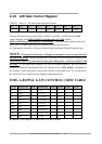
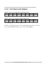
2.4.5 Clear Interrupt Request
(WRITE) Base+8 : Clear Interrupt Request Format
Bit 7 Bit 6 Bit 5 Bit 4 Bit 3 Bit 2 Bit 1 Bit 0
X X X X X X X X
X=don‘t care, XXXXXXXX=any 8 bits data is validate
If the OME-A-822PGL/PGH is used in the interrupt transfer mode, an on-board hardware
status bit will be set after each A/D conversion. This bit must be cleared by software before
the next hardware interrupt. Writing any value to address BASE+8 will clear this hardware
bit and the hardware will generate another interrupt when next A/D conversion is completed.
OME-A-822PGL/PGH Hardware Manual ---- 19