


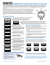
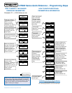

The LVR300 Series’ programming ring can be rotated from the Neutral center position to
Position 1 and Position 2. The following actions are possible:
A – Display of parameters with Position 1 (simultaneous display of the set parameters) –
Turn the programming ring left to Position 1 to begin cycling through these programming
parameters: Switching points S1 and S2, Hysteresis direction of S1 and S2,
Hysteresis Hyst 1 and Hyst 2, Code (allows editing of additional parameters),
Filter, Units, Output, 4 mA Value and 20 mA value. See following pages for
detailed programming instructions.
B – Editing with Position 2
Turn the programming ring to the right to Position 2 and a flashing cursor
appears showing the position to be changed. With repeated turning to
Position 2, the values are increased. By turning to Position 1, you obtain
the next position. Each position can be edited in this way. If there is no
action within 5 seconds, the device returns to the normal display sec-
tion without the change being accepted, and you will have to cycle
through the program again.
C – Saving the change with Position 1
Turning one time toward Position 1 after quitting the last value signifies
acceptance of the change.
Programming protection:
The programming ring can be pulled off,
inverted and replaced. This will prevent further
programming resulting from turning the ring in
either direction.
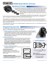
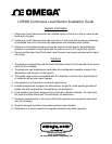
The complete LVR300 Series Sensor is designed to be a self-contained continuous level sen-
sor and control, requiring only a power source. A 16-bit microcontroller with a 14-bit A/D
converter and a 12-bit D/A converter provides the necessary processing speed and
measurement accuracy. The signal is displayed with units using a back-lit LCD
graphical display and converted to a 4-20 mA signal. Two switch points
with either a positive or negative output can be programmed over the com-
plete range.
The switching point hysteresis can be set separately in value and direction
(minimum/maximum switching value). Upward and downward crossings of switching points and error messages are
shown in the display with a flashing red LED that is easily visible from a distance.
Other parameters can be changed using codes, including: signal filter; selectable unit (inch, cm) includes automatic con-
version of the values; selectable 0-20 mA or 4-20 mA output; value assignment of 4-20 mA (setting of zero point and
span). The complete housing can be rotated around the mechanical connection so that the correct reading position can be
set after mounting (installation).
This LVR300 Series is very easy to use, as dialog messages are displayed for the user. It can even be set when wearing
protective gloves, if necessary.
Operating Principle
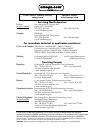
© Copyright Omega Engineering Inc. – 4/05
All specifications are subject to change without notice.
LVR300 Series Sensor Overview
Programming Overview
Value
S1 max.
Alarm range
Hyst 1
Time
Value
S1 min.
Time
Hyst 1
Alarm range
Terminal Assignment
The switch points are automatically chang-
ing to positive or negative, depending on
your interface.
Mating Connector
M12 x 1, 5-position female, shielded, straight or
M12 x 1, 5-position female, shielded, right angle
Sources: Hirschmann, Binder,
rde Connectors & Cables or
comparable connector
S2
S1
24 to 30 VDC
0 V
4-20 mA
LVR
Sensor
white
brown
gray
black
blue
z
z
Z = load
1
2
3
4
5
z
or
NPNExample: PNP
Programming Ring turns from
Position 1 to Position 2
Example of hysteresis setting:
Examples with S1 as maximum switching point
and as minimum switching point: