


© Copyright Omega Engineering Inc. – 4/05
All specifications are subject to change without notice.
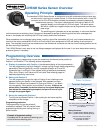
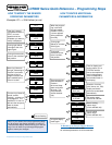
LVR300 Series Programming Positions & Operation
On power-up, the company logo is displayed, followed by the preset level/unit measurement. Changing the level (by float movement)
will be reflected in the display. If the level is at either of the preset switch levels S1 or S2 (the upper and lower levels), the display will
also be alternating between the S1 (or S2) status indication with the level reading. The Switch Active status is also indicated by a
flashing LED.
By rotating the program ring to Position 1 (P1, toward the left) and then back to Neutral, the pro-
gram steps to the S1 setting. The level for activation of the S1 switch is indicated, and may be
edited by turning the program ring to the P2 position (see below). This will highlight the tenths
digit. The digit value is advancing by alternating the program ring from center to the right P2
position. Turning the ring to the P1 position accepts that value and moves to the next digit.
Turning the ring to Neutral and then back to P1 will cycle through all of the digits and then accept the
values.
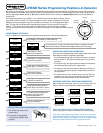
PROGRAMMING POSITIONS
The P1 to Neutral movement steps the program through positions in the following sequence:
Program
Position 1
Program
Position 2
Neutral
1
2
###.#
Inches (cm)
###.#
<S1
S1
###.#
S1
Min. (Max.)
Hyst 1
##.#
S2
###.#
S2
Max. (Min.)
Hyst 2
##.#
Code
000
###.#
Inches (cm)
Filter
##.#
Units
Inch (cm)
Output
4-20 mA
Logo display, only shown on initial power-up.
Current float level. At right, the switch active status is indicated and alter-
nates with the regular measurement display, and the LED is flashing.
Switch point 1 is active if the level
is below (or below) S1.
Switch point 2 is active if the level
is above (or below) S2.
Switch point 1 value,
sets level for activation.
Hysteresis threshold added to
switch point 1 for switch = active.
Hysteresis threshold added to
switch point 2 for switch = active.
Returns to regular display
of current float level.
To access other program para-
meters, rotate ring to P2
and change 000 to 111.
Switch point 2 value,
sets level for activation.
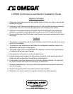
MODIFYING OPERATING PARAMETERS
From any of the Programming Position steps noted at left, follow
these steps to modify the operating parameter:
1 Turn the programming ring to the right to Position 2, and then
back to Neutral, to bring up the editing cursor in the first deci-
mal place.
2 Turning the ring to the right and back to Neutral increases the
current decimal place to the next highest value.
3 Turning the ring to the left and back to Neutral moves the cur-
sor on to the next decimal position. Repeat step 2 to edit the
current position.
4 To confirm the new value, continue to turn the ring to the left
and back to neutral until you cycle through all of the decimal
places and the next parameter shows on the display.
ENTERING ADDITIONAL PROGRAM PARAMETERS
After reaching the Code step, enter 111 by turning the ring P1 to
Neutral, and you can access these additional parameters:
OR
Note: During the programming process, if there is no new action
taken within 30 seconds, the sensor will return to “measurement
display” without saving your changes. You will have to go through
the entire program a second time to re-program the unit.
Time for the mea-
surement to
respond (seconds)
Switch between inches
and cm; Switch points are
converted automatically
Switchable to
0-20 mA
123
4 mA
###.#
20 mA
###.#
###.#
Inches (cm)
Set the 4 mA level
(may be higher than
the min. level)
Set the
20 mA level
Returns to regular dis-
play mode
456
Enter Code 989 to return to Factory Default Settings.
Step-by-step program examples are illustrated on the following pages.
PROTECTING YOUR PROGRAMMING PARAMETERS
1. Pull off the ring. Keep it as a
personal key.
2. Use ring in reverse position
on the sensor (PROG.LOCK
position).
LOGO