


LVR300 Continuous Level Sensor Installation Guide
General Information
1. Continuous Level Sensors should be installed rigidly so the float is free to move as the
liquid level changes.
2. Continuous Level Sensors should be mounted in a tank area free of severe turbulence
or protected from such turbulence by appropriate and adequate slosh shields.
3. Continuous Level Sensors stems should be vertical for best results, but satisfactory
operation is possible in most liquids with the stem at up to a 30º angle from vertical.
4. Care should be taken that Continuous Level Sensors are always operated within electri-
cal ratings.
Cautions
1. The pressure, temperature and electrical limitations shown for the specified level sensor
must not be exceeded.
2. The pressures and temperatures must take into consideration possible surges in the
temperature and pressure of the system.
3. The liquids used must be compatible with the materials of construction. Specifications
of materials will be given upon request.
4. Life expectancy of the sensor varies with applications.
5. Ambient temperature changes can affect sensor set points, since specific gravities of
liquids vary with temperature. Consult factory for assistance.
6. Level sensors have been designed to be shock and vibration resistant. For maximum
life, both should be minimized. Consult factory for assistance.
7. Excessive contaminants in fluid may inhibit float operation and occasional wipe down
may be necessary.
8. Physical damage to product may render product unserviceable.
9. Installation in a vessel made from magnetic materials may affect operation.
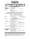
Shop online at: omega.com
e-mail: info@omega.com
For latest product manuals: omegamanual.info