


Page 20
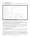
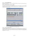
3.4.5.4 Updating the NMM Firmware via FTP
Using an FTP application, upload the new firmware into the FTP root directory of the NMM. When the file
transfer is complete, the NMM verifies the file and then automatically restarts with the newly loaded
firmware.
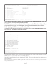
For detailed instructions on updating the management modules and other modules in the same chassis via
FTP, download the application note “iConverter Management: Updating Modules via FTP” available on
Omnitron’s web page:
http://www.omnitron-systems.com/downloads.php
See Setting NMM Passwords, Section 3.4.1.4, on how to configure FTP.
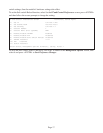
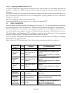
3.5 VERIFY OPERATION
Once the module has been installed and configured, per Sections 3.2 - 3.4, verify the module is operational
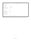
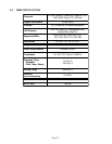
by viewing the status of the LED indicators. The table below provides a description for each indicator.
The Power LED indicates the module is receiving power from the chassis. The NMM has an LED indicator
for each available power supply in the chassis (19-Module Chassis has three, 5-Module Chassis has two).
The Master/Slave and Management LEDs indicate the operation and configuration of the management
channel. A blinking “Mgt” LED indicates the NMM is polling the chassis.
The UTP “Lk/Rx” LED indicates the module has established a connection across its UTP port. A blinking
LED indicates the presence of data.
Refer to Section 6.0, Troubleshooting Guide, for help in determining possible fault conditions.
LED Function
"Legend"
Color Off State On / Blinking State
Power "Pwr" Amber No power Module has power
Power Supply
#1 Status
"PS1"
Amber
Power Supply #1 not
installed
On: Power available from installed Power
Supply #1
Blinking: No power available from installed
Power Supply #1
Power Supply
#2 Status
"PS2"
Amber
Power Supply #2 not
installed
On: Power available from installed Power
Supply #2
Blinking: No power available from installed
Power Supply #2
Power Supply
#3 Status
"PS3"
Amber
Power Supply #3 not
installed
On: Power available from installed Power
Supply #3
Blinking: No power available from installed
Power Supply #3
Network Ports Status
Management
Mode "Msr/Slv"
Green Slave Mode Master Mode
Management
Polling "Mgt"
Green No Polling Activity Management Polling Activity
Management
Port Link and
Activity "Lk/Rx"
Green No Link
On: 10Mbps UTP Port Link is active (via
either UTP or Backplane Port A)
Blinking: UTP Port Data Activity