


A-70 Guard Lock Safety-door Switch D4BL
D4BL
Safety Door
Switches
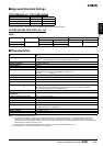
Solenoid Coil Characteristics
Indicator Characteristics
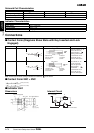
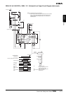
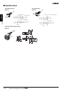
Connections
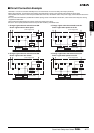
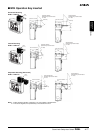
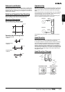
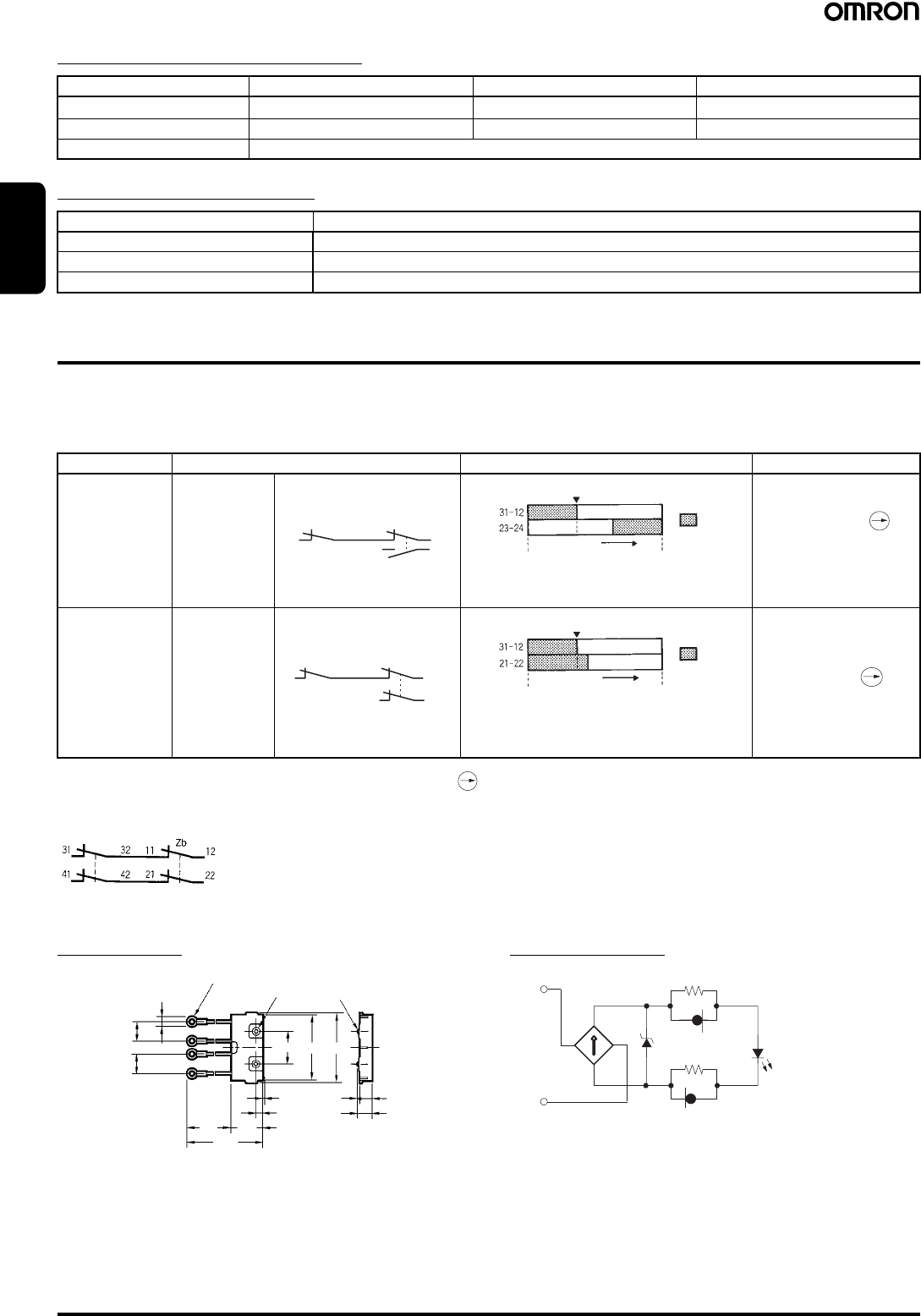
■ Contact Form (Diagrams Show State with Key Inserted and Lock
Engaged)
Note: The EN-approved direct opening mechanism is indicated by on the Switch.
■ Contact Form 2NC + 2NC
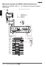
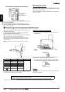
■ Indicator Unit
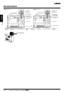
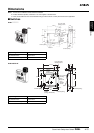
Dimensions Internal Circuit
Item 24-VDC mechanical lock models 110-VAC mechanical lock models 24-VDC solenoid lock models
Rated operating voltage
24 VDC
(100% ED) 110 VAC ±10% (50/60 Hz) 24 VDC (100% ED)
Current consumption Approx. 300 mA Approx. 98 mA Approx. 300 mA
Insulation Class F (130
°C or less)
+10%
−15%
+10%
−15%
Item LED
Rated voltage 10 to 115 VAC/VDC
Current leakage Approx. 1 mA
Color (LED) Orange, green
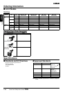
Model Contact Operating pattern Remarks
D4BL-@C@@-@ 1NC/1NO+1NC
D4BL-@D@@-@ 2NC+1NC
31
32 11
12
24
23
Zb
Stroke
ON
Lock position
Operation Key
insertion comple-
tion position
Extraction
completion
position
Only NC contacts 11-12
and 31-32 have an
approved direct
opening mechanism.
The terminals 11-12
and 23-24 can be
used as unlike poles.
12
22
113231
21
Zb
Stroke
ON
Lock position
Operation Key
insertion comple-
tion position
Extraction
completion
position
NC contacts 11-12,
21-22, and 31-32
have an approved
direct opening
mechanism.
The terminals 11-12
and 21-22 can be
used as unlike poles.
(Safety circuit side)
(Monitor circuit side)
(16)
(16)
(7)
(35) 26.2
(61.2)
0.3
5.6
26.8
53.2 57.2
2 10.6
(12.6)
Two, 7 dia.
Four terminal plates
Two LED indicators
R
Z
D
R
LED
10 to 115 VAC/DC
Constant-current diode