


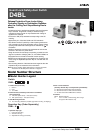
Guard Lock Safety-door Switch D4BL A-75
D4BL
Safety Door
Switches
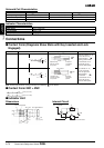
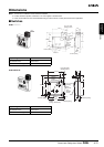
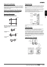
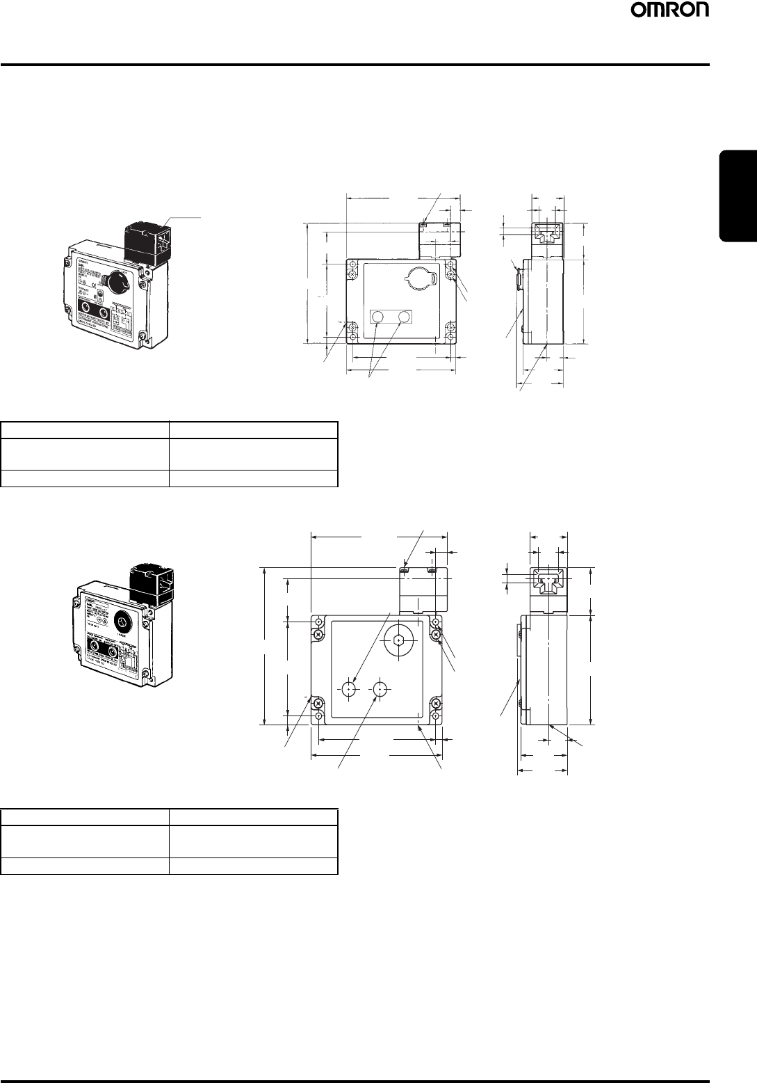
Dimensions
Note: 1. All units are in millimeters unless otherwise indicated.
2. Unless otherwise specified, a tolerance of
±0.4 mm applies to all dimensions.
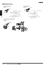
3. There are fluctuations in the contact ON/OFF timing for 2NC contacts. Confirm performance before application.
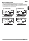
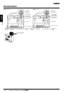
■ Switches
100±0.1
74±0.1
112
+1
0
86
+1
0
34.2
(123.5)
6.8
(116.5)
10
15
5.5
7
37.5
31.5
17
16
39.6
46.3
Conduit opening
Indicators
Conduit opening
Cover
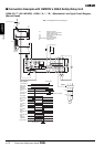
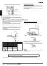
D4BL-@@@@-@
Red
Four, M3.5 head
clamping screws
Lock
protection
cap
Four, 5.3 dia.
mounting
holes
Four, M4
cover
clamping
screws
Operating Characteristics D4BL-@@@@
Key insertion force
Key extraction force
19.61 N max.
19.61 N max.
Movement before being locked 15 mm max.
31.5
17
7
37.5
86
+1
0
112
+1
0
16
39.6
42.6
Conduit opening
Conduit opening
Indictor
(Orange: Switch OFF)
Indicator
(Green:
Solenoid ON).
5.5
Conduit opening
(116.5)
10
34.2
74
±0.1
100
±0.1
6.8
(123.5)
Cover
Four, 5.3 dia.
Mounting
holes
Four, M3.5 head
clamping screws
Four, M4
cover
clamping
screws
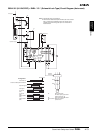
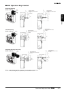
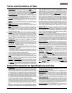
D4BL-2GRD-AT
Operating Characteristics D4BL-2GRD-AT
Key insertion force
Key extraction force
19.61 N max.
19.61 N max.
Movement before being locked 15 mm max.