


Guard Lock Safety-door Switch D4BL A-71
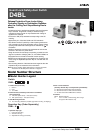
D4BL
Safety Door
Switches
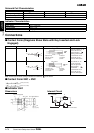
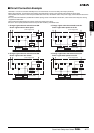
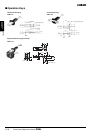
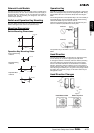
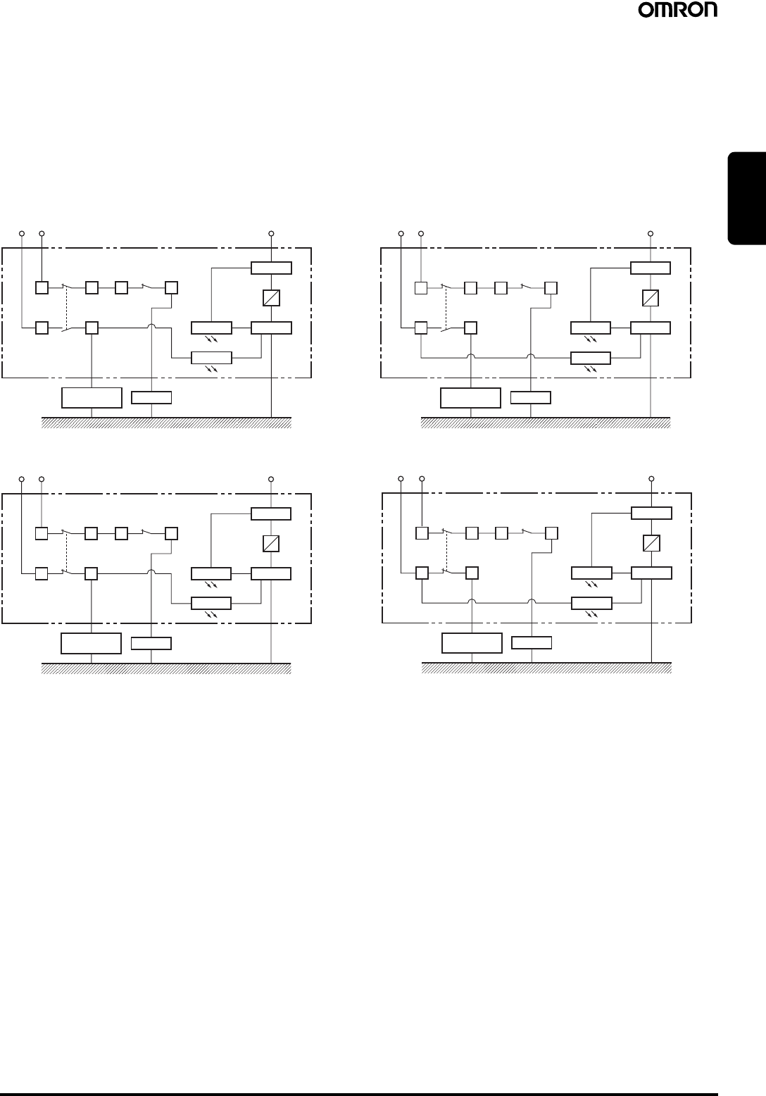
■ Circuit Connection Example
• Terminals 11 and 32 are connected internally and so connect terminals 12 and 31 for safety-circuit input. (GS-ET-19).
• When using indicators, connect them to the auxiliary circuit side (monitor circuit) or the solenoid input terminals as shown below.
• The indicators can be used to confirm the open/closed status of the door, the ON/OFF status of the power supply, and the ON/OFF status of the
solenoid.
• Do not connect the indicators in parallel with the direct opening contact. If the indicators are broken, a short-circuit current may flow, causing
equipment to malfunction.
• The 24-VDC solenoid terminals have polarity. Confirm the polarity before wiring.
• Be sure to use a special pushbutton switch to stop and start machinery and release locks.
1211 32
E2 (−)
E1 (+)
31
23 24
1211 32
E2 (−)
E1 (+)
31
23 24
1211 32
E2 (−)
E1 (+)
31
21 22
1211 32
E2 (−)
E1 (+)
31
2221
1. Orange: Lights when the solenoid turns ON.
Green: Lights when the door opens.
(Power supply side)
Solenoid
LED (orange)
LED (green)
Auxiliary circuit
(monitor circuit)
Safety circuit
(Ground side)
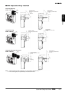
2. Orange: Lights when the solenoid turns ON.
Green: Lights when power turns ON.
(Power supply side)
Solenoid
LED (orange)
LED (green)
Auxiliary circuit
(monitor circuit)
Safety circuit
(Ground side)
3. Orange: Lights when the solenoid turns ON.
Green: Lights when door closes.
(Power supply side)
Solenoid
LED (orange)
LED (green)
Auxiliary circuit
(monitor circuit)
Safety circuit (Ground side)
4. Orange: Lights when the solenoid turns ON.
Green: Lights when power turns ON.
(Power supply side)
Solenoid
LED (orange)
LED (green)
Auxiliary circuit
(monitor circuit)
Safety circuit (Ground side)