


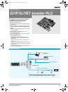
366 3G3RV-P10ST@-E
PLC inverter
Specifications by product
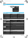
General specifications
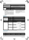
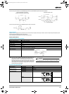
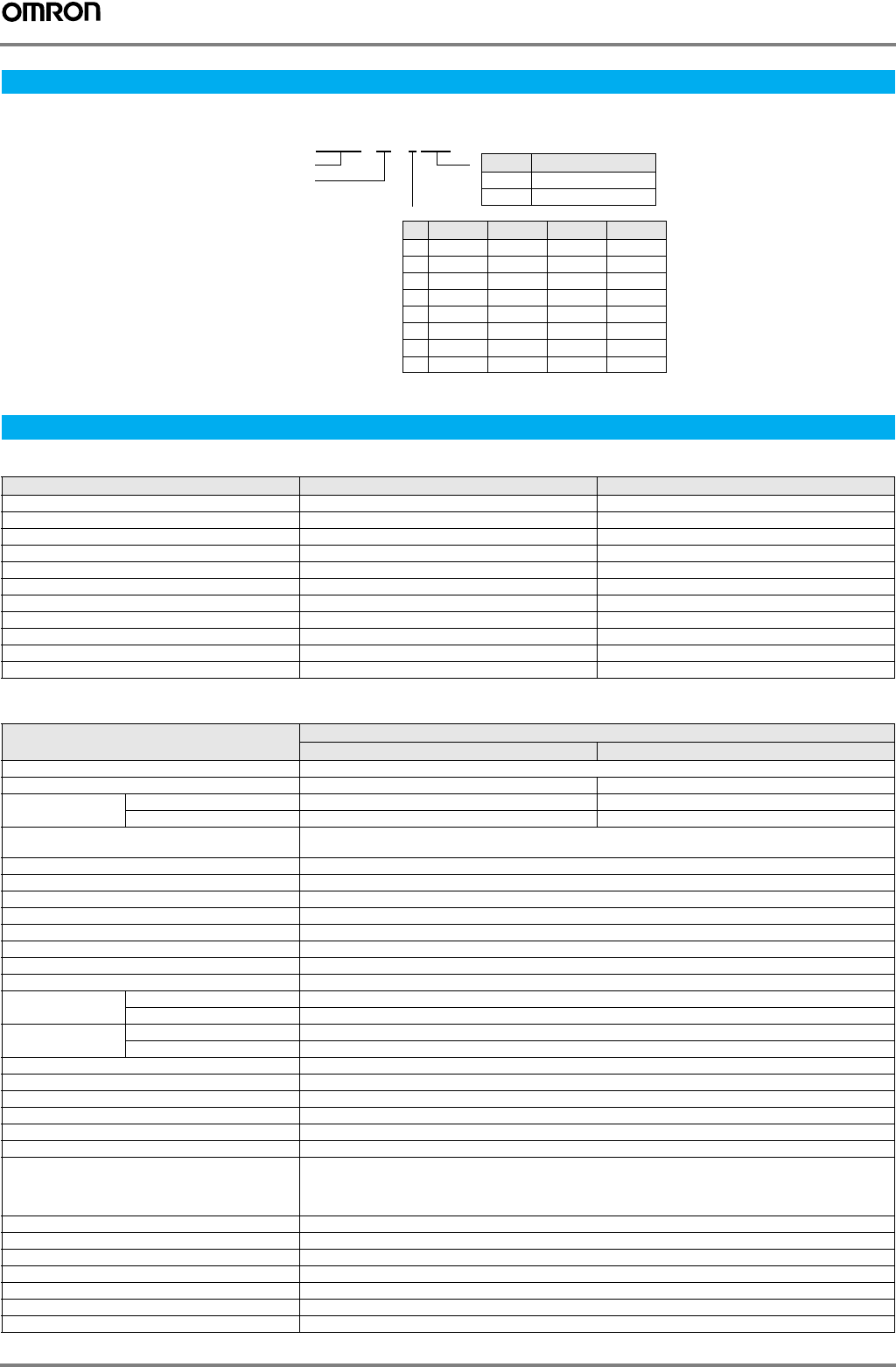
Type designation
Specifications
Item 3G3RV-P10ST8-E 3G3RV-P10ST8-DRT-E
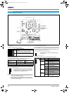
PLC core CPM2C-S CPM2C-S
Inputs 6 24 VDC inputs 6 24 VDC inputs
Outputs 4 sourcing/PNP transistor outputs 4 sourcing/PNP transistor outputs
Peripheral port Yes Yes
RS-232C port Yes Yes
RS-422 port No Yes
Calendar/clock Yes Yes
Memory backup Flash memory and battery Flash memory and battery
Compobus/S master interface Yes Yes
Encoder interface Yes Yes
DeviceNet Slave interface No Yes
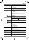
Item Specifications
3G3RV-P10ST8-E 3G3RV-P10ST8-DRT-E
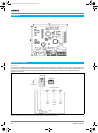
Rated power supply voltage 24 VDC
+10%
/
-15%
(external power supply for I/O)
Communications power supply voltage --- 11 to 25 VDC (supplied by communications connector)
Power consumption
supply
Internal power 2 W (supplied internally) (see note) 3 W (supplied internally) (see note)
Communications power supply --- 30 mA max.
Vibration resistance 10 to 20 Hz, 9.8 m/s2 max.
20 to 50 Hz, 2 m/s2 max
Ambient operating temperature -10 to 45 °C
Ambient operating relative humidity 10% to 90% (no condensation)
Ambient storage temperature -20 to 70 °C
Atmosphere Must be free from corrosive gas
Control method Store program method
I/O control method Cyclic scan method
Programming language Ladder chart method
Instruction length 1 step/1 instruction; 1 to 5 words/1 instruction
Instruction types Basic 14 types (same as for programmable slaves)
Special 105 types, 185 instructions (same as for programmable slaves)
Processing speed Basic instructions 0.64 µs (LD)
Special instructions 7.8 µs (MOV)
Program capacity 4,096 words
Maximum number of I/O points 10
Input bits 00000 to 00015 (6 physical inputs)
Output bits 01000 to 01003 (4 physical outputs)
CompoBus/S input bits 128 bits: IR 02000 to IR 02715 (bits not used for CompoBus/S input bits can be used for work bits.)
CompoBus/S output bits 128 bits: IR 03000 to IR 03715 (bits not used for CompoBus/S output bits can be used for work bits.)
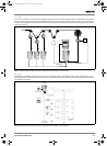
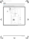
Inverter interface Direct interface with inverter through
• IR-memory
• DM-memory
• Transfer command
Inverter interface bits 176 bits: IR 20000 to IR 21015
Encoder interface bits 48 bits: IR 02900 to IR 02915 and IR 04800 to IR 04915
Work bits 448 bits: IR 02800 to IR 02815, IR 03800 to IR 04715, and IR 21100 to IR 22715
Special bits (SR area) 448 bits: SR 22800 to SR 25507 (words SR 228 to SR 255)
Temporary bits (TR area) 8 bits (TR 0 to TR 7)
Holding bits (HR area) 320 bits: HR 0000 to HR 1915 (words HR 00 to 19)
Auxiliary bits (AR area) 384 bits: AR 0000 AR 2315 (words AR 00 to AR 23)
3G3RV-P10ST8-DRT-E
Inverter series
Number of I/O's
Options
DeviceNet slave
-No
DRT Yes
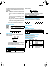
Output RTC RS422 Remarks
- NPN NO NO
1NPN NO YES
2 NPN YES NO
3 NPN YES YES
5 PNP NO NO
6 PNP NO YES
7PNP YES NO
8 PNP YES YES Standard
Y203-EN2-02-Katalog.book Seite 366 Mittwoch, 24. Mai 2006 2:22 14