


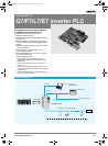
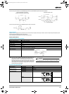
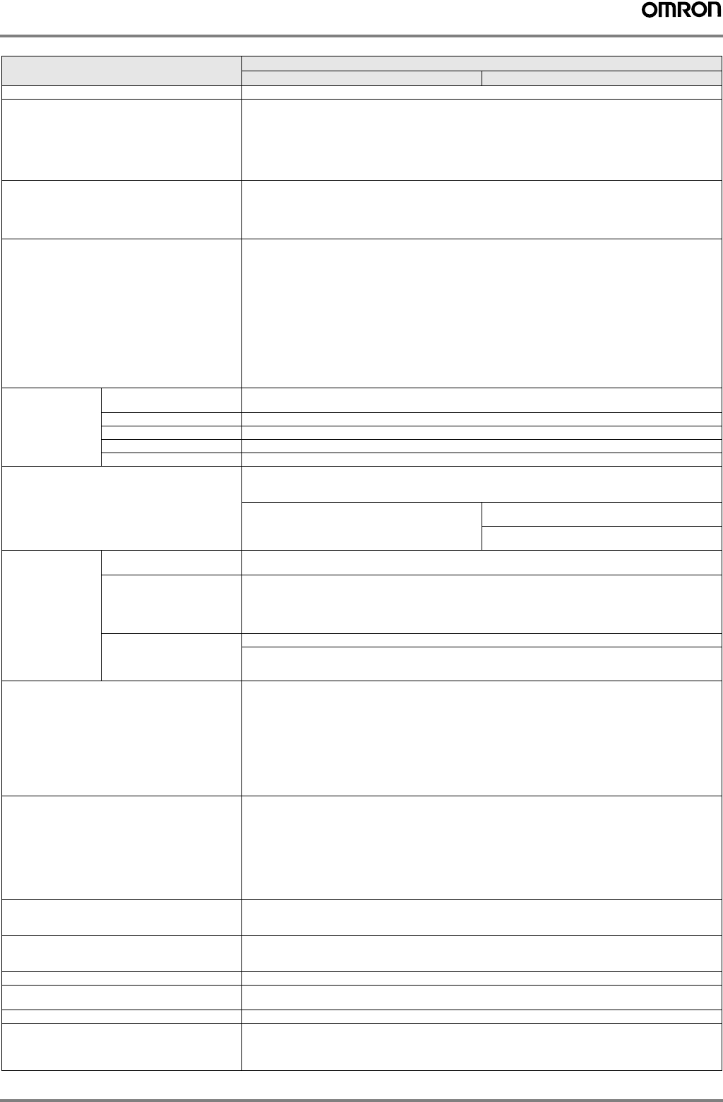
G7/F7/L7/E7 inverter PLC 367
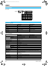
Link bits (LR area) 256 bits: LR 0000 to LR 1515 (words LR 00 to LR 15)
Timers/counters 256 timers/counters (TIM/CNT 000 to TIM/CNT)
1-ms timers: TMHH(--)
10-ms timers: TIMH(15)
100-ms timers: TIM
1-s/10-s timers: TIML(--)
Decrementing counters: CNT
Reversible counters: CNTR(12)
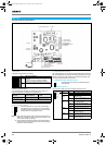
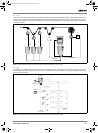
CompoBus/S master functions Remote I/O devices can be allocated up to 256 I/O points (128 inputs and 128 outputs) in input area IR 020 to
IR 027 and output area IR 030 to IR 037.
• The node numbers can be set to 0 to 7 (128-point mode) or 0 to 15 (256-point mode).
• The communications mode can be set to high-speed mode (max. length 100 m) or long-distance mode
(max. length 500 m).
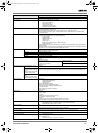
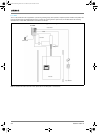
DeviceNet slave functions Up to 64 words (32 input words and 32 output words) can be allocated to the DeviceNet master's I/O.
The master's I/O can be allocated to the following data areas:
IR 000 to IR 049
IR 200 to IR 227
DM 0000 to DM 2047
LR 00 to LR 15
HR 00 to HR 19
AR 00 to AR 23 (3G3RV-P10ST ' master; read-only)
TC 000 to TC 255
• Explicit message communications are supported. Any 3G3RV-P10ST data area can be accessed from the
DeviceNet master.
• The communications speed can be set to 500 kbps (total network length 100 m max.), 250 kbps (total network
length 250 m max.), or 125 kbps (total network length 500 m max.).
DM area Read/write 2,029 words (DM 0000 to DM 0999, DM 1019 to DM 2047)
DM 2000 to DM 2021: error log storage area
Read only 456 words (DM6144 to 6599)
Inverter interface 19 words (DM 2022 to DM 2040)
Encoder interface 14 words (DM 1986 to DM 1999)
PLC setup 56 words (DM 6599 to DM 6655)
Interrupts Interrupt inputs
2 inputs
Response time: 50 µs
Interval timer interrupts
1 input
Set value: 0.5 to 319,968 ms
Precision: 0.1 ms
Scheduled interrupts
One-shot interrupt
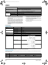
High-speed counters High-speed counter 1 input,
see note 5
No interrupt
Differential phase mode (5 kHz)
Pulse plus direction input mode
(20 kHz)
Up/down input mode (20 kHz)
Increment mode (20 kHz)
Count-check interrupt
(An interrupt can be generated when the count equals the set value or the count lies within a preset range.)
Interrupt inputs (counter mode)
2 inputs
Incrementing counter (2 kHz)
Decrementing counter (2 kHz)
No interrupt
Count-up interrupt
Encoder interface 3 input modes:
Differential-phase (up/down)
Pulse plus direction
Up/down pulse
Maximum input frequency 50 kHz
Maximum counter range 4,294,967,295 (232-1)
Two capture registers, 3 selectable registration inputs
One comparison value
Counter reset through software or Z-phase
Interrupt function
Pulse outputs • 2 outputs:
Single-phase pulse output without acceleration/deceleration (see note 6.)
10 Hz to 10 kHz
• 2 outputs:
Variable duty ratio pulse output (see note 6.)
0.1 to 999.9 Hz, duty ratio 0 to 100%
• 1 output:
Pulse output with trapezoidal acceleration/deceleration (see note 6.)
Pulse plus direction output, up/down pulse output, 10 Hz to 10 kHz
Synchronized pulse control 1 point, see notes 5 and 6
Input frequency range: 10 to 500 Hz, 20 Hz to 1 kHz, or 300 Hz to 20 kHz
Output frequency range: 10 Hz to 10 kHz
Pulse catch inputs 2 bits
Minimum pulse input: 50 µs max.
Used in common by input interrupts and input interrupt counter mode.
Analog volume None
Input time constant
(ON response time = OFF response time)
Determines the input time constant for all inputs. (settings: 1, 2, 3, 5, 10, 20, 40, or 80 ms)
Clock/Calendar function Shows the current year, month, day of the week, day of the month, hour, minute, and second.
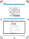
Communication function Port 1 = Peripheral and RS-422:
Host link, peripheral bus, no-protocol, programming console
Port 2 = RS-232C port:
Host link, no-protocol, 1:1 PLC link, 1:1 NT link
Item Specifications
3G3RV-P10ST8-E 3G3RV-P10ST8-DRT-E
Y203-EN2-02-Katalog.book Seite 367 Mittwoch, 24. Mai 2006 2:22 14