


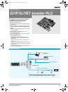
368 3G3RV-P10ST@-E
Note: 1. The DM area, HR area, AR area, and counter values are
backed up. If the backup battery or capacitor is discharged,
the contents of these areas will be lost and the data values will
revert to the defaults.
2. The contents of the program area, read-only DM area
(DM6144 to DM6599), and PLC setup (DM 6600 to DM 6655)
are stored in flash memory. The contents of these areas will
be read from flash memory the next time the power is turned
ON, even if the backup battery or capacitor is discharged.
When data has been changed in any of these areas, write the
new values to flash memory by switching the 3G3RV-P10ST
to MONITOR or RUN mode, or by turning the power OFF and
then ON again.
3. Changes made while in MONITOR mode using, for example,
online editing, are written to flash memory in real-time.
4. The above figure for power consumption includes the power
consumption of the programming console.
5. This input is shared by the high-speed counter and synchro-
nized pulse control functions.
6. This output is shared by the pulse output and synchronized
pulse control functions.
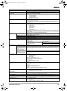
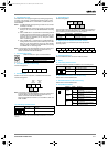
I/O specifications
Input specifications
Note: The input time constant can be set to 1, 2, 3, 5, 10, 20, 40, or 80 ms in the PLC setup.
High-speed counter inputs
The following unit input bits can be used as high-speed counter inputs. The maximum count frequency is 5 kHz in differential phase mode and
20 kHz in the other modes.
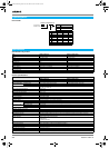
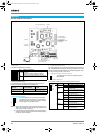
Power-interruption hold function Holds the contents of HR, AR, CNT, and DM areas.
Memory backup (see notes 1 and 2.) Flash memory: Program, read-only DM area, and PC setup
Memory backup: The read/write DM area, HR area, AR area, and counter values are backed up.
(The battery has a 5-year lifetime at 25 °C and it is replaceable.)
Self-diagnostic function CPU errors, memory errors, communications errors, setting errors, battery errors
Program check No END instruction, program errors (regularly checked during operation)
Connected tools CX-programmer After version 2.1
Programming console C200H-PRO27, CQM1-PRO01
SSS PC98 & PC/AT (SYSMAC support software, all versions)
CX-drive Version 1 or higher
Item Specifications
3G3RV-P10ST8-E 3G3RV-P10ST8-DRT-E
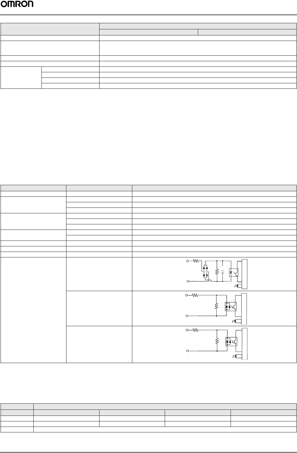
Item Inputs Specification
Input voltage All 24 VDC
+10%
/
-15%
Input impedance IN 00000 to IN 00001 2.7 kΩ
IN 00002 to IN 00004 3.9 kΩ
IN 00005 4.7 kΩ
Input current IN 00000 to IN 00001 8 mA typical
IN 00002 to IN 00004 6 mA typical
IN 00005 5 mA typical
ON voltage/current IN 00000 to IN 00001 17 VDC min., 5 mA
IN 00002 to IN 00005 14.4 VDC min., 3.5 mA
OFF voltage/current All 5.0 VDC max., 1.1 mA
ON delay All 1 to 80 ms max. Default: 10 ms (see note.)
OFF delay All 1 to 80 ms max. Default: 10 ms (see note.)
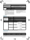
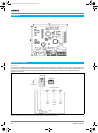
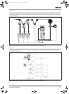
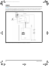
Circuit configuration IN 00000 to IN 00001
IN 00002 to IN 00004
IN 00005
IN
COM
1kΩ
0.01
µF
Input LED
Internal circuits
2.7 kΩ
IN
COM
820 Ω
Input LED
Internal circuits
3.9 kΩ
IN
COM
750 Ω
Input LED
Internal circuits
4.7 kΩ
Input Function
Differential phase mode Pulse plus direction input mode Up/down input mode Increment mode
IN 00000 A-phase pulse input Pulse input Increment pulse input Increment pulse input
IN 00001 B-phase pulse input Direction input Decrement pulse input Normal input
IN 00002 Z-phase pulse input or hardware reset input (IN00002 can be used as a normal input when it is not used as a high-speed counter input.)
Y203-EN2-02-Katalog.book Seite 368 Mittwoch, 24. Mai 2006 2:22 14