


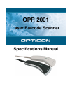


Opticon
OPR 2001
Specifications Manual
5
15.1. Auto Trigger Settings .....................................................................................................38
15.1.1. Stand Only ............................................................................................................................. 38
15.1.2. Always.................................................................................................................................... 39
15.1.3. Manually................................................................................................................................. 39
16. Regulatory Compliance ........................................................................................................40
16.1. Laser Safety...................................................................................................................40
16.2. Product Safety ...............................................................................................................40
16.3. EMC...............................................................................................................................40
16.4. Compliance to RoHS .....................................................................................................40
17. Safety .....................................................................................................................................41
17.1. Shock.............................................................................................................................41
17.2. Temperature Conditions ................................................................................................41
17.3. Foreign Materials ...........................................................................................................41
17.4. Other..............................................................................................................................41
18. Mechanical Drawing..............................................................................................................42
Table of Figures
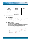
Figure 1: Ambient light immunity .................................................................................................9
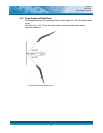
Figure 2: Laser scanning tilt and curvature ............................................................................... 11
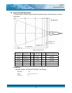
Figure 3: Depth of field. .............................................................................................................13
Figure 4: Pitch ...........................................................................................................................14
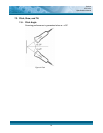
Figure 5: Skew angle and dead zone ........................................................................................15
Figure 6: Tilt angle .....................................................................................................................16
Figure 7: Curvature....................................................................................................................17
Figure 8: Interface circuit...........................................................................................................19
Figure 9:Character format (same for both sending and receiving) ............................................20
Figure 10: Communication format .............................................................................................20
Figure 11: No handshaking........................................................................................................20
Figure 12: Busy/Ready communication.....................................................................................21
Figure 13: Cannot receive command ........................................................................................21
Figure 14: Signal timing.............................................................................................................22
Figure 15: Modem transmit data................................................................................................22
Figure 16: ACK/NAK..................................................................................................................23
Figure 17: ACK/NAK—No response..........................................................................................24
Figure 18: USB "A" connector ...................................................................................................25
Figure 19: Interface circuit.........................................................................................................26
Figure 20: DOS/V host connector..............................................................................................27
Figure 21: DOS/V keyboard connector......................................................................................27
Figure 22: RS-232C cable .........................................................................................................28
Figure 23: USB cable ................................................................................................................28