


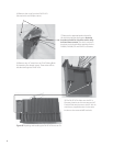
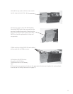
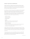


• Install the various covers in this order with the DCC or Turbo last:
(1) DC battery terminals
(2) FW-ACA (if used)
(3) AC Wiring Compartment
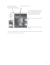
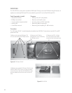
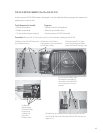
Figure 16:
After wiring, install all covers.
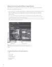
The surge protector’s DC + and DC-
cables and the BATT TEMP sensor cable
pass under this rubber bushing
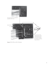
The system can now be powered up
• DC power lights up the surge protector’s DC ACTIVE LED
• AC OUTPUT from the FX will light up the AC OUT ACTIVE LED
• AC INPUT from a utility grid or generator will light the AC IN ACTIVE LED
• Initially, if any ERROR LED lights, check all wiring and inspect the surge protector circuit board
for damage. If no damage or wiring problems are found but the ERROR light stays lit, please
contact OutBack Technical Services
• Check the surge protector periodically and particularly after any suspected surge event. If an
ERROR occurs, replace the board with an FW-SP-R or contact OutBack Technical Services
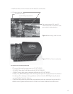
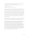
Figure 17: DCC or Turbo is installed last.
17