


10
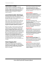
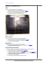
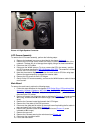
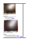
Picture 14. Main Board Screws
Translation Board
The translation board is a small PCB with a USB, VGA-Out and AC adapter connector. To
remove it, perform the following steps:
1. Perform all steps to remove the main board (see chapter Main Board
).
2. Remove the screw holding the translation board.
3. Lift out the translation board.
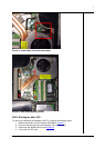
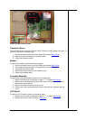
Modem
To remove the modem, perform the following steps:
1. Perform all steps to remove the main board (see chapter Main Board
).
2. On the main board, the modem is located next to the mini PCI slot.
3. Disconnect the modem cable.
4. Remove the 2 small screws of the modem board.
5. Remove the modem board.
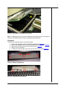
Touchpad Assembly
To remove the touchpad assembly, perform the following steps:
1. Remove the top cover as described in steps 1 - 7 in chapter Main Board
.
2. Remove the 12 screws securing the metal shield to the top cover. Note that 3
screws are covered with foil.
3. Remove the metal shield from the top cover.
4. Gently push out the touchpad board. Keep in mind that this is glued to the top
cover.
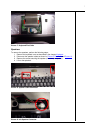
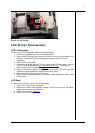
LCD Switch
To remove the LCD switch, perform the following steps:
1. Remove the top cover as described in steps 1 - 7 in chapter Main Board
.
2. Remove the screw of the LCD switch (Picture 15
).